Electro Tech is an online community (with over 170,000 members) who enjoy talking about and building electronic circuits, projects and gadgets. To participate you need to register. Registration is free. Click here to register now.
Welcome to our site! Electro Tech is an online community (with over 170,000 members) who enjoy talking about and building electronic circuits, projects and gadgets. To participate you need to register. Registration is free. Click here to register now.
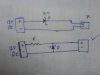
In the top circuit the zener is forward biased, therefor it is not acting like a zener, it is simply providing ~0.6v of a voltage drop. That's probably why there's an "X" mark after the circuit.
In the second circuit the zener will operate properly as a simple shunt regulator if "R" is correctly chosen. That's probably why it has a "√" mark after it.
Cellphone draws significant current 300 mA for small voice only to 1000 mA for smartphone. The best way to go from 12v to 5v at this amount of current is with a switching regulator.
There are many very inexpensive cigarette lighter charger adaptors on the market to do this job.
hi, in cell phone repair the charging ic replacment is not easy therefre a zener diod is used but in series main idea is to directly connect 5v dc charger + line to battery which is 3.6 vdc this is not a good idea but we have to do this. i know that it is wrong but teacher says use zener in series circuit.i want to know the value of resister to drop 5vdc to 3.6 vdc through zener diod.
No one came back yet so if it helps a zener diode dumps voltage to negative. So if you want 3.6 V on the line then the zener must be 12V-3.6V= 8.4V.
8.4V will dump to neg leaving 3.6V to use-I think that's how it goes
Better put some current limiting in though however suits. Say 100 ohms on the top line and 100 ohms on the zener line would allow a reasonable current to flow
If the 12v input is not adequately filtered/regulated for the expected load then all the crap that rides on the 12v line will appear on the 3.6v output of the zener. All the zener is doing is subtracting 8.4v from whatever is fed into it.
If you have a 12v supply and take 8.4v away for a zener then 3.6v more for a phone, there is no more voltage left for a current limiting resistor.
This site uses cookies to help personalise content, tailor your experience and to keep you logged in if you register.
By continuing to use this site, you are consenting to our use of cookies.