Electro Tech is an online community (with over 170,000 members) who enjoy talking about and building electronic circuits, projects and gadgets. To participate you need to register. Registration is free. Click here to register now.
Welcome to our site! Electro Tech is an online community (with over 170,000 members) who enjoy talking about and building electronic circuits, projects and gadgets. To participate you need to register. Registration is free. Click here to register now.
Fatal error: Allowed memory size of 8388608 bytes exhausted (tried to allocate 131072 bytes) in /home/httpd/vhosts/electro-tech-online.com/httpdocs/includes/functions_search.php on line 187!!
any ideas?
I am trying to post this one as a new post:
Hi all,
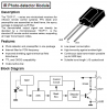
Built a photodiode circuit (refer schematic Figure 1 - Link below) to recieve pulses - square wave on "on" period 10us with varyin duty cycles incident on the photodiode(BP104).
On testing the circuit, found the output at the trans-resistance amplifier had some ringing at the edges (refer 2nd figure - 1st response). The further the distance of the incident signal from the transmitter, the more pronounced the ringing.
Any ideas as to what is causing this?
ooops sori read it now - i need to make a few posts in order to be allowed to start a new thread!!
Krud.. that doesnt leave me in a good situation at all
Your transistor circuit is shorting the output of the photodiode.
Every photodiode amplifier circuit in Google that uses the photodiode with reversed bias like yours has the photodiode direct-coupled to the opamp's input without a coupling capacitor. The opamp's negative feedback resistor has a very high value for high gain and is a high resistance bias feed to the photodiode.
The ringing is fixed with a small-value capacitor across the opamp's negative feedback resistor.
the gyrator acts as a constant current source. It has a time constant such that it is not fast enough to react to the incident pulse of IR (10us), hence giving me a low (square wave) signal at the photodiode.
It serves to filter out ambient light or any other form of IR interference.
The transistor must have DC current through it for it to be a gyrator. It has only the tiny leakage current of the photodiode so it isn't doing anything.
The circuit should have a high resistance feedback resistor for the opamp for high gain and this resistor should bias the photodiode.
Why not use a TSOP IR receiver IC instead of re-inventing the wheel?
The transistor must have DC current through it for it to be a gyrator. It has only the tiny leakage current of the photodiode so it isn't doing anything.
My understanding was that the capacitor C1 is charged up and controls the base of the transistor. R1 and C1 have a time constant associated with them.
so when a pulse of frequency of interest (100KHz) is incident on the photodiode, the transistor deprives the diode of supply due to the large time constant of R1-C1.
so if this theory is right shouldnt the "gyrator" (i might be using the wrong terminology) filter out ambient sources of IR?
audioguru said:
The circuit should have a high resistance feedback resistor for the opamp for high gain and this resistor should bias the photodiode.
I do have a high resisitance feedback resisitor R5, or so i thought! am i wrong? in this case i am looking to get a Vout = Iin * Rfb, which is 68000V/A
audioguru said:
Why not use a TSOP IR receiver IC instead of re-inventing the wheel?
I want to implement multiples of this reciever circuit. so it has to be cost effective. ( i am also tryin to replace the AD817AN with a cheaper op-amp.. i used it cuz it was handy and it sufficed the rquirements)
I can't start a new thread either so I will post it here...Nigel or any other mod please feel free to move it if you can start it in a new thread. I get the same error as Crush described...
Hello everyone,
I have been doing some electrolysis experiments lately and I need a strong power supply that has a high current (50A or higher) and low voltage of 6 volts. Is there a simple circuit off of 120VAC mains I can put together to make this work easily and cheaply. I think the easiest way would be to use 2N3055 since they are good for 15A, so a few of these together would suffice I assume. I don't know how to go about increasing current though.
Your very low gain circuit barely works as "FAR" away as only 5cm. Is that anywhere near as good as a modern TV's remote that uses a TSOP IR receiver IC for its 10m range?
For your power supply topic, look at the current gain of a 2N3055. At only 10A its minimum current gain is only 5, and the datasheet doesn't talk about any higher current. It saturates poorly at 10A even with a whopping 3.3A of base current.
Your very low gain circuit barely works as "FAR" away as only 5cm. Is that anywhere near as good as a modern TV's remote that uses a TSOP IR receiver IC for its 10m range?
Sorry my fault, i must have been more specific. I thought i had written too much already.
The range i require is only 5 cm.
I am transmitting unique ID's:
10us on, 10 us off - ID 1
10us on, 20 us off- ID 2
and so on..
At the moment i am just simply turnin the transmitter on and off with a fixed "on" period an duty cycle. It is controlled by a simple program toggling the pins of a micro which is controlling the mosfet to the transmitter LED.
Photoreciever modules work on carrier frequencies, which would mean i would have to modulate my transmitted signal with a carrier frequency.
so using a module would mean i wld have to shift away from the workings i have until now.
Or is it an easy shift?
Now I'm getting frustrated - I see some people are able to start a new thread in this forum with no previous posts so why am I getting this fatal error message?
I'm trying to design a simple circuit that cuts-off when the current through a time-varying load falls below a threshold value.
Basically, I am electrochemically etching a piece of wire, which initially has a resistance of ~1k Ohms. When the etching is complete the resistance rapidly (few 100ms) increases to essentially an open circuit, at which point I want to automatically break the circuit. The etching requires a constant voltage of ~3V dc.
I think I can use some sort of comparator circuit, but I'm not sure how best to implement this - any assistance would be appreciated!
pass a constant current through the wire and measure the voltage across it using a comparator , when the resistance increases , the voltage will also increase which you can detect
This site uses cookies to help personalise content, tailor your experience and to keep you logged in if you register.
By continuing to use this site, you are consenting to our use of cookies.