Continue to Site

Welcome to our site!

Electro Tech is an online community (with over 170,000 members) who enjoy talking about and building electronic circuits, projects and gadgets. To participate you need to register. Registration is free. Click here to register now.

  • Welcome to our site! Electro Tech is an online community (with over 170,000 members) who enjoy talking about and building electronic circuits, projects and gadgets. To participate you need to register. Registration is free. Click here to register now.

XM Satellite Radio Project

Status
Not open for further replies.

bruner

New Member
I don't know anything about antenna theory, so I'm really hoping someone can help me out on this.

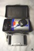
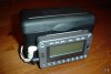
I just got one of the newer XM Radio "Roady2" units which has a built in FM transmitter. This way you don't have to hard-wire it into your existing car stereo. It's intended to be mounted on your dashboard...

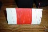
What I did, was build a little battery box out of a plastic index card holder from Staples, that holds a 6v lantern battery and the satellite antenna so that I can make it more portable. The problem is that the built in FM transmitter is not strong enough to send a signal as far as I would like it to.

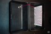
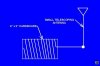
The built in FM antenna is nothing more than a "loop" of metal suspended above the PCB on the interior of the XM reciever. I was hoping that a simple coil of wire placed directly behind the XM reciever would "catch" the signal and that I could re-direct that signal to a small telescoping antenna, thus getting more range out of it.

I tried two versions of this idea, one using a short length of wire and one using 50 feet of wire, both wrapped around a piece of cardboard. Neither seemed to have any affect at all.

Is this there any way to improve upon this idea?

This message and the following few mesages should have some pictures attached.

Any help would be greatly appreciated.

Thanks,
Dan
8)
 

Attachments

  • 02.jpg
    02.jpg
    25.3 KB · Views: 1,159
  • 01_335.jpg
    01_335.jpg
    26.9 KB · Views: 1,139
More Pictures...
 

Attachments

  • 04.jpg
    04.jpg
    27.2 KB · Views: 1,138
  • 03.jpg
    03.jpg
    21.1 KB · Views: 1,145
More pictures...
 

Attachments

  • 06.jpg
    06.jpg
    20.3 KB · Views: 1,149
  • 05.jpg
    05.jpg
    29.4 KB · Views: 1,136
Two days and no replies?

Doesn't anyone have any suggestions on this?

I could realy use some help.

Thanks,
Dan
 
First is there anyway you can tell if the signal is getting to the external antannae if so you could probably build an OP amp and boost the output of the signal. Only idea I could come up with at the moment not exactly an expert in this area but still learning. Be careful because the FM is a liscense only band and normally most of those devices are working to their maximum legal distance. Once they start causing interference to other devices and radiostations it becomes a problem with the FCC.
 
magickaldan, there aren't laws about how powerful a receiver you can use... a powerful receiver isn't going to cause interference since it's not transmitting anything.
 
evandude said:
magickaldan, there aren't laws about how powerful a receiver you can use... a powerful receiver isn't going to cause interference since it's not transmitting anything.

If you havn't read the original post, he's not trying to strengthen the XM Receiver but make the signal go farther on the built in FM transmitter.
 
oops! sorry. I skimmed the original post and misread what he was trying to do here. I thought he was trying to boost the XM radio reception, rather than the FM transmitter range.
 
Well, as far as whether or not the signal from the XM is getting picked up by the coil and directed to my telescoping antenna, I can't tell... There is no marked improvement in distance of reception.

I like the OP amp idea, but I was hoping that I could avoid anything too complicated. Perhaps there is a way of making a coil that acts as a sort of transformer, "stepping up" the output of the telescoping antenna?

I don't even know if my original coil idea is a step in the right directionl. I just assumed that it might work, but like I said, I'm not getting any good results.

By the way, checked out your website magickaldan, and from one Dan to another, nice work ;)

If you're curious, here's my website:
http://www.geocities.com/danielbruner/

Dan
:)
 
bruner said:
Well, as far as whether or not the signal from the XM is getting picked up by the coil and directed to my telescoping antenna, I can't tell... There is no marked improvement in distance of reception.

There won't be, it's not a workable idea.

I like the OP amp idea, but I was hoping that I could avoid anything too complicated. Perhaps there is a way of making a coil that acts as a sort of transformer, "stepping up" the output of the telescoping antenna?

You can't use an opamp for something like this, you would need an RF power amplifier.

I don't even know if my original coil idea is a step in the right directionl. I just assumed that it might work, but like I said, I'm not getting any good results.

You would need to remove the original aerial, and replace it with a better one, making sure it's tuned to the correct frequency and matched to the impedance of the transmitter. The design of the transmitter is probably such that this could be quite difficult, it's only designed for extremely short range - adding a better aerial probably won't make a huge difference.

How far are wanting to extend it?.
 
I'd be tempted to clip a 6 inch length of wire to the antenna to see what happens - possibly adding a capacitor (10 pf maybe) or small air variable to uncouple any DC. It might or might not cause stability problems with the transmitter. What you've shown is actually quite the popular way to couple an AM receiving antenna to an AM radio with an internal loopstick. I could be wrong but the inductance of your coil is likely to be an impediment at FM frequencies.

As I recall regulations here in US limit power and antenna length but my info may be out of date.

The right way to do it - design an antenna that will efficiently radiate where you want it to radiate. Couple the antenna to a proper transmission line so that all of the power from the line goes to the antenna. Couple the transmission line properly to the transmitter output. The net effect of all this should be efficient transmitter operation, low line loss and low losses in the antenna system. All of this is a lot of work and may net you an antenna configuration that is impractical for your situation. You'll be forced to compromise. Experimentation, just as you are doing, might get you to an acceptable solution with less work.
 
Thanks guys, I appreciate the response and the suggestions.

Since I use the XM in both my truck and on this battery box, I wanted to avoid any kind of "direct" connection to the internall antenna.

Perhaps I'll try a solid metal plate in place of the coil and see what that does.

It's a shame the output of the built in antenna isn't just a bit stronger... The reason behind the idea is that I can only get a sattellite signal from a south facing window and our office (where the boombox is) is on the north side of the house about 20-30 feet away (thru some walls).

Dan
:)
 
I have an Idea I don't know if you want to do it but here it goes. First you get a FM receiver that can pick up the signal from the FM transmitter inside the XM unit then buy/build a new FM transmitter to retransmit the signal to a farther distance. There are many FM transmitter circuits on this board and on the internet and a simple FM radio will do the trick as the Reciever. It's a little more complicated but should do the trick. I havn't actually tried this but I've seen it done for Wireless Internet so It should be probable for this.
 
It seems to me that the trick would be to AVOID amplification since it MIGHT be illegal to boost the OUTPUT of the FM transmitter.
The diagram I'm ( hopefully ) attaching shows a way to COUPLE the external antenna to the FM transmitter .
The copper foil will act like a capacitor. The thickness and dialectric properties of the sat radios case will determine the SIZE of the copper foil pads , and you will have to experiment for best coupling.
the telescope antenna should be between 10 to 19 inches in length.
the trimmer capacitor is used to TUNE the network for resonance.

IF the FM RECIEVER you are planning on useing is going to be a DEDICATED reciever ( MAIN purpose is to recieve the output of the sat radio ) you might want to look into PEAKING the thing for BEST reception on the sat radios OUTPUT frequency.

Hope that helps
 

Attachments

  • external_coupling.gif
    external_coupling.gif
    4.9 KB · Views: 826
Status
Not open for further replies.

Latest threads

New Articles From Microcontroller Tips

Back
Top