Continue to Site

Welcome to our site!

Electro Tech is an online community (with over 170,000 members) who enjoy talking about and building electronic circuits, projects and gadgets. To participate you need to register. Registration is free. Click here to register now.

  • Welcome to our site! Electro Tech is an online community (with over 170,000 members) who enjoy talking about and building electronic circuits, projects and gadgets. To participate you need to register. Registration is free. Click here to register now.

XLCD with PIC18f452

Status
Not open for further replies.
I have been trying to interface 16x2 lcd but failing. I am new to MPLAB so its sort of frustrating. I searched various forums so it came to my knowledge that xc8 has plib so i can use xlcd.h for my intentions.

Now the problem is the program compiles fine. But there is nothing on lcd and not even the lcd pins toggle. I added PORTC toggle to see if my code is working and it was. Onlything that is not working is LCD.

After changing the PIN configuration in xlcd.h i included it in project also pic18f452.h and recompiled and there was success building it too. Please see the code and proteus image to help me out.
xlcd.h
Code:
#ifndef __XLCD_H
#define __XLCD_H
#include "p18cxxx.h"
/* PIC18 XLCD peripheral routines.
 *
 *   Notes:
 *      - These libraries routines are written to support the
 *        Hitachi HD44780 LCD controller.
 *      - The user must define the following items:
 *          - The LCD interface type (4- or 8-bits)
 *          - If 4-bit mode
 *              - whether using the upper or lower nibble
 *          - The data port
 *              - The tris register for data port
 *              - The control signal ports and pins
 *              - The control signal port tris and pins
 *          - The user must provide three delay routines:
 *              - DelayFor18TCY() provides a 18 Tcy delay
 *              - DelayPORXLCD() provides at least 15ms delay
 *              - DelayXLCD() provides at least 5ms delay
 */

/* Interface type 8-bit or 4-bit
 * For 8-bit operation uncomment the #define BIT8
 */
/* #define BIT8 */

/* When in 4-bit interface define if the data is in the upper
 * or lower nibble.  For lower nibble, comment the #define UPPER
 */
/* #define UPPER */

/* DATA_PORT defines the port to which the LCD data lines are connected */
 #define DATA_PORT      		PORTB
 #define TRIS_DATA_PORT 		TRISB

/* CTRL_PORT defines the port where the control lines are connected.
 * These are just samples, change to match your application.
 */
 #define RW_PIN   LATBbits.LATB6   		/* PORT for RW */
 #define TRIS_RW  TRISBbits.TRISB6    	/* TRIS for RW */

 #define RS_PIN   LATBbits.LATB4   		/* PORT for RS */
 #define TRIS_RS  DDRBbits.TRISB4    	/* TRIS for RS */

 #define E_PIN    LATBbits.LATB5  		/* PORT for D  */
 #define TRIS_E   DDRBbits.TRISB5    	/* TRIS for E  */

/* Display ON/OFF Control defines */
#define DON         0b00001111  /* Display on      */
#define DOFF        0b00001011  /* Display off     */
#define CURSOR_ON   0b00001111  /* Cursor on       */
#define CURSOR_OFF  0b00001101  /* Cursor off      */
#define BLINK_ON    0b00001111  /* Cursor Blink    */
#define BLINK_OFF   0b00001110  /* Cursor No Blink */

/* Cursor or Display Shift defines */
#define SHIFT_CUR_LEFT    0b00000100  /* Cursor shifts to the left   */
#define SHIFT_CUR_RIGHT   0b00000101  /* Cursor shifts to the right  */
#define SHIFT_DISP_LEFT   0b00000110  /* Display shifts to the left  */
#define SHIFT_DISP_RIGHT  0b00000111  /* Display shifts to the right */

/* Function Set defines */
#define FOUR_BIT   0b00101100  /* 4-bit Interface               */
#define EIGHT_BIT  0b00111100  /* 8-bit Interface               */
#define LINE_5X7   0b00110000  /* 5x7 characters, single line   */
#define LINE_5X10  0b00110100  /* 5x10 characters               */
#define LINES_5X7  0b00111000  /* 5x7 characters, multiple line */

#ifdef _OMNI_CODE_
#define PARAM_SCLASS
#else
#define PARAM_SCLASS auto
#endif

#ifndef MEM_MODEL
#ifdef _OMNI_CODE_
#define MEM_MODEL
#else
#define MEM_MODEL far  /* Change this to near for small memory model */
#endif
#endif

/* OpenXLCD
 * Configures I/O pins for external LCD
 */
void OpenXLCD(PARAM_SCLASS unsigned char);

/* SetCGRamAddr
 * Sets the character generator address
 */
void SetCGRamAddr(PARAM_SCLASS unsigned char);

/* SetDDRamAddr
 * Sets the display data address
 */
void SetDDRamAddr(PARAM_SCLASS unsigned char);

/* BusyXLCD
 * Returns the busy status of the LCD
 */
unsigned char BusyXLCD(void);

/* ReadAddrXLCD
 * Reads the current address
 */
unsigned char ReadAddrXLCD(void);

/* ReadDataXLCD
 * Reads a byte of data
 */
char ReadDataXLCD(void);

/* WriteCmdXLCD
 * Writes a command to the LCD
 */
void WriteCmdXLCD(PARAM_SCLASS unsigned char);

/* WriteDataXLCD
 * Writes a data byte to the LCD
 */
void WriteDataXLCD(PARAM_SCLASS char);

/* putcXLCD
 * A putc is a write
 */
#define putcXLCD WriteDataXLCD

/* putsXLCD
 * Writes a string of characters to the LCD
 */
void putsXLCD(PARAM_SCLASS char *);

/* putrsXLCD
 * Writes a string of characters in ROM to the LCD
 */
void putrsXLCD(const char *);

/* User defines these routines according to the oscillator frequency */
extern void DelayFor18TCY(void);
extern void DelayPORXLCD(void);
extern void DelayXLCD(void);

#endif

main.c
Code:
#include <p18cxxx.h>
#include <plib/xlcd.h> 
#include <delays.h> 
#include <xc.h>

/* Set configuration bits for use with ICD2 / PICDEM2 PLUS Demo Board:
* - set HS oscillator
* - disable watchdog timer
* - disable low voltage programming
*/
#pragma config OSC = HS
#pragma config WDT = OFF
#pragma config LVP = OFF

#define _XTAL_FREQ 20000000UL

void DelayFor18TCY(void)
 {
 Delay10TCYx(0x2); //delays 20 cycles
 return;
 }
 /*****/
 void DelayPORXLCD(void)   // minimum 15ms
 {
 Delay100TCYx(0xA0);   // 100TCY * 160
 return;
 }
 /*****/
 void DelayXLCD(void)     // minimum 5ms
 {
 Delay100TCYx(0x36);      // 100TCY * 54
 return;
 }

void main(){

	PORTC = 0X00;
	TRISC = 0X00;
	OpenXLCD(FOUR_BIT & LINES_5X7);
    WriteDataXLCD('H');
	WriteCmdXLCD(DON&CURSOR_OFF&BLINK_OFF);
	while(1)
		{
			PORTC=~PORTC;  //LED off for a short time to show we are looping
			while(BusyXLCD()); 
			Delay10KTCYx(250); 
			putrsXLCD("Lcd Testing.."); 
		}	
}	
**broken link removed**
 

Attachments

  • s.PNG
    s.PNG
    44.5 KB · Views: 2,159
Hi,

Have you got through the part where the LCD shows its cursor first? Or are you just using it straightforward without going through the tutorials?

If not, then this tutorial is excellent before you start using libraries.

Cheers.
Vizier87
 

Attachments

  • lcd1.pdf
    240.7 KB · Views: 1,631
The only way I can use the XLD library is to copy and paste the source code AND header into MY working directory.. For some reason ( and don't know why ) the #define 8BITS... never gets defined..... So the library never works....
 
can you share your working project?

I also observed in MPLAB X Ide that when i simulate the code step by step the program gets halt at OpenXLCD(FOUR_BIT & LINES_5X7); i do not know why even that i have done
#define FOUR_BIT 0b00101100 /* 4-bit Interface */
#define LINES_5X7 0b00111000 /* 5x7 characters, multiple line */

Also i thought it may be havint trouble navagiting to openxlcd so in included its c file but then gives compile time error that no rule to make openxlcd.p1 etc

i am confused
 
Make a new C file and chuck all the routines in it... Then the header will work as well..

Put both these in the working directory..
 

Attachments

  • xlcd.c
    26.3 KB · Views: 1,156
  • xlcd.h
    4 KB · Views: 1,003
Make a new C file and chuck all the routines in it... Then the header will work as well..

Put both these in the working directory..

Added those files and got errors
Code:
CLEAN SUCCESSFUL (total time: 110ms)
make -f nbproject/Makefile-default.mk SUBPROJECTS= .build-conf
make[1]: Entering directory `F:/Projects/Embedded Systems/ATS/PIC18/MPLAB/test1/xlcd.X'
make  -f nbproject/Makefile-default.mk dist/default/production/xlcd.X.production.hex
make[2]: Entering directory `F:/Projects/Embedded Systems/ATS/PIC18/MPLAB/test1/xlcd.X'
"C:\Program Files (x86)\Microchip\xc8\v1.12\bin\xc8.exe" --pass1  --chip=18F452 -Q -G --asmlist  --double=24 --float=24 --emi=wordwrite --opt=default,+asm,-asmfile,+speed,-space,-debug,9 --addrqual=ignore -P -N255 --warn=0 --summary=default,-psect,-class,+mem,-hex,-file --output=default,-inhx032 --runtime=default,+clear,+init,-keep,-no_startup,-download,+config,+clib,+plib "--errformat=%%f:%%l: error: %%s" "--warnformat=%%f:%%l: warning: %%s" "--msgformat=%%f:%%l: advisory: %%s"  -obuild/default/production/_ext/1472/xlcd.p1  ../xlcd.c 
C:\Program Files (x86)\Microchip\xc8\v1.12\include\plib\xlcd.h:53: warning: redefining preprocessor macro "TRIS_RS" (C:\Program Files (x86)\Microchip\xc8\v1.12\include\plib\xlcd.h: 44)
C:\Program Files (x86)\Microchip\xc8\v1.12\include\plib\xlcd.h:56: warning: redefining preprocessor macro "TRIS_E" (C:\Program Files (x86)\Microchip\xc8\v1.12\include\plib\xlcd.h: 47)
../xlcd.c:203: error: "," expected
../xlcd.c:204: error: type redeclared
../xlcd.c:204: error: conflicting declarations for variable "putrsXLCD" (C:\Program Files (x86)\Microchip\xc8\v1.12\include\plib\xlcd.h:146)
(908) exit status = 1
make[2]: *** [build/default/production/_ext/1472/xlcd.p1] Error 1
make[1]: *** [.build-conf] Error 2
make[2]: Leaving directory `F:/Projects/Embedded Systems/ATS/PIC18/MPLAB/test1/xlcd.X'
make[1]: Leaving directory `F:/Projects/Embedded Systems/ATS/PIC18/MPLAB/test1/xlcd.X'
make: *** [.build-impl] Error 2

BUILD FAILED (exit value 2, total time: 1s)
The files you sent were not modified in anyway
 
No My Main is totaly empty no include statement. I am doing a test project in empty project. please see the image attached. Things are getting real crazyMPLAB.png
 
It is still looking for the xlcd.h in the wrong place.... Check all your code and make sure that xlcd.h IS in the working directory..

I moved files to core project folder and yet following errors appear
Code:
CLEAN SUCCESSFUL (total time: 51ms)
make -f nbproject/Makefile-default.mk SUBPROJECTS= .build-conf
make[1]: Entering directory `F:/Projects/Embedded Systems/ATS/PIC18/MPLAB/test1/xlcd.X'
make  -f nbproject/Makefile-default.mk dist/default/production/xlcd.X.production.hex
make[2]: Entering directory `F:/Projects/Embedded Systems/ATS/PIC18/MPLAB/test1/xlcd.X'
"C:\Program Files (x86)\Microchip\xc8\v1.12\bin\xc8.exe" --pass1  --chip=18F452 -Q -G --asmlist  --double=24 --float=24 --emi=wordwrite --opt=default,+asm,-asmfile,+speed,-space,-debug,9 --addrqual=ignore -P -N255 --warn=0 --summary=default,-psect,-class,+mem,-hex,-file --output=default,-inhx032 --runtime=default,+clear,+init,-keep,-no_startup,-download,+config,+clib,+plib "--errformat=%%f:%%l: error: %%s" "--warnformat=%%f:%%l: warning: %%s" "--msgformat=%%f:%%l: advisory: %%s"  -obuild/default/production/main.p1  main.c 
xlcd.h:74: error: bad storage class
(908) exit status = 1
make[2]: *** [build/default/production/main.p1] Error 1
make[1]: *** [.build-conf] Error 2
make: *** [.build-impl] Error 2
make[2]: Leaving directory `F:/Projects/Embedded Systems/ATS/PIC18/MPLAB/test1/xlcd.X'
make[1]: Leaving directory `F:/Projects/Embedded Systems/ATS/PIC18/MPLAB/test1/xlcd.X'

BUILD FAILED (exit value 2, total time: 282ms)
 
Oh dear... You have moved onto the XC8 compiler.... The code posted was originally targeted to the C18..


I have given you C18 code..... I'll have a go at it tonight... I'll post a library that works with XC8...
 
Oh dear... You have moved onto the XC8 compiler.... The code posted was originally targeted to the C18..


I have given you C18 code..... I'll have a go at it tonight... I'll post a library that works with XC8...

I tried to work this library on C18 but still does not work :p 
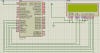
i suppose things are against me
 
Hi,

Hope I'm not hijacking the thread. Had several attempts at getting XLCD working without success. Always had trouble with file locations, like the OP.

Followed Ian's suggestions about creating one 'C' file with all the functions in it and finally have had success.

**broken link removed**

**broken link removed**

Code:
/*  01:42 28 April 2013
*
*   E:\Electronics\PIC Projects\MCP Forum\XLCD\Source Files\XLCD Main.c
*
*   xc8 v1.12
*
*   PIC18F2420
*
*   Tested ok on 2 x 16 LCD
*
*/


#include <xc.h>
#include "My_xlcd.h"
/*------------------------------------------------------------------------*/

#pragma config CONFIG1H = 0X08;
#pragma config CONFIG2L = 0X19;
#pragma config CONFIG2H = 0X1E;
#pragma config CONFIG3H = 0X01; // MCLRE ON = 0x81, OFF = 0x01
#pragma config CONFIG4L = 0X80;


/*------------------------------------------------------------------------*/

#define _XTAL_FREQ (4000000)    /* Not using xtal, only to make delays work as
                                    it won't compile without this */


void DelayFor18TCY(void);
void DelayPORXLCD(void);
void DelayXLCD(void);

/*------------------------------------------------------------------------*/

void main (void)
{
    OSCCON = 0b01100010;            // Fosc = 4MHz (Inst. clk = 1MHz)
    ADCON1 = 0xF;                   // No analog, all digital i/o
    TRISA = 0x00;
    TRISB = 0x0;
    TRISC = 0x0;
    LATB = 0x0;


while(1)
{

    OpenXLCD(FOUR_BIT & LINES_5X7 & CURSOR_ON & BLINK_ON);
    while(BusyXLCD());

    WriteCmdXLCD(SHIFT_DISP_LEFT);
    while(BusyXLCD());

    WriteDataXLCD('A');
    while(BusyXLCD());

    WriteDataXLCD('t');
    while(BusyXLCD());

    WriteDataXLCD(' ');
    while(BusyXLCD());

    putrsXLCD( "last! XLCD," );
    while(BusyXLCD());

    WriteCmdXLCD(0xC0);
    while(BusyXLCD());

    putrsXLCD( "thanks Ian" );
    while(BusyXLCD());

    while(1);

    }

 }
/*------------------------------------------------------------------------*/
void DelayFor18TCY(void)
{
    __delay_us(18);

    }

/*------------------------------------------------------------------------*/
void DelayPORXLCD(void)
{
     __delay_ms(15);

    }
/*------------------------------------------------------------------------*/
void DelayXLCD(void)
{
    __delay_ms(5);

    }
/*------------------------------------------------------------------------*/

P.S. I found that the way to stop the compiler always looking to the XLCD.h in the xc8 directory was to clear the option below....

**broken link removed**
 

Attachments

  • XLCD Main.c
    2.1 KB · Views: 815
  • My_XLCD.c
    25.4 KB · Views: 857
  • My_xlcd.h
    4.2 KB · Views: 851
Last edited:
LCD and PIC18f452

Hello there
After getting frustrated for nearly two weeks with xlcd i found a library for lcd. Even with the help https://www.electro-tech-online.com/threads/xlcd-with-pic18f452.134227/#post1124166 here i could not make it work The problem was that the output never showed up on LCD in proteus. The pins toggled but no output also the pin no 4 of LCD always remained 0.

Now the funny part is that with this library that i have found i get the desiplay at Proteus but not in real hardware. The hardware is tested by the example written in MikroC. If a MikroC example can make it work why not C18?

Also i noticed that with the attached library the when circuit is powered off the lcd gets initilized because the top row of boxes vanish. I have few brand new LCDs and tested to make sure there is nothing wrong with the hardware. I cant figure out where i am not doing it the way it should be.

Code:
#ifndef __HD44780_H
#define __HD44780_H

//******************************************
//  Library for control LCD HD44780        *
//  Mode Control 4 bits                    * 
//  By Hector                              *
//  http://www.youtube.com/user/Hector8389 *
//****************************************** 

#include <p18f452.h>     // Select your MCU
#include <stdio.h>
#include <stdlib.h>
#include <string.h>
#include <delays.h>

/////////////////////////////////////////////
//                                         //
// Configure your MCU. Any mode            //
// Pin Set digital mode. your code         //
//                                         //
/////////////////////////////////////////////	

#define LCD_RD7     LATBbits.LATB0      // D7     
#define TRIS_RD7    TRISBbits.TRISB0    

#define LCD_RD6     LATBbits.LATB1      // D6
#define TRIS_RD6    TRISBbits.TRISB1

#define LCD_RD5     LATBbits.LATB2      // D5
#define TRIS_RD5    TRISBbits.TRISB2

#define LCD_RD4     LATBbits.LATB3      // D4
#define TRIS_RD4    TRISBbits.TRISB3

#define LCD_EN     LATBbits.LATB4       // EN
#define TRIS_EN    TRISBbits.TRISB4

#define LCD_RS     LATBbits.LATB5       // RS
#define TRIS_RS    TRISBbits.TRISB5


/////////////////////////////////////////////
//                                         //
// Available Lcd Commands                  //
//                                         //
/////////////////////////////////////////////

#define      LCD_FIRST_ROW           128
#define      LCD_SECOND_ROW          192
#define      LCD_THIRD_ROW           148
#define      LCD_FOURTH_ROW          212
#define      LCD_CLEAR               1
#define      LCD_RETURN_HOME         2
#define      LCD_CURSOR_OFF          12
#define      LCD_UNDERLINE_ON        14
#define      LCD_BLINK_CURSOR_ON     15
#define      LCD_MOVE_CURSOR_LEFT    16
#define      LCD_MOVE_CURSOR_RIGHT   20
#define      LCD_TURN_OFF            0
#define      LCD_TURN_ON             8
#define      LCD_SHIFT_LEFT          24
#define      LCD_SHIFT_RIGHT         28


void Lcd_Init(void);
void Lcd_Out(unsigned char y, unsigned char x, const rom char *buffer);
void Lcd_Out2(unsigned char y, unsigned char x, char *buffer);
void Lcd_Chr_CP(char data);
void Lcd_Cmd(unsigned char Cmd);

void Delay_5us(void);
void Delay_5500us(void);


/////////////////////////////////////////////
//                                         //
// Set delays, based on the                // 
// frequency of a XTAL.                    //
//                                         //
/////////////////////////////////////////////

void Delay_5us(void){
// Delay of 5us
// Cycles = (5us * 20MHz) / 4
// Cycles = 25
// Put 25 more  
Nop(); Nop(); Nop(); Nop(); Nop(); Nop(); Nop(); Nop(); Nop(); Nop();
Nop(); Nop(); Nop(); Nop(); Nop(); 
Nop(); Nop(); Nop(); Nop(); Nop(); Nop(); Nop(); Nop(); Nop(); Nop();
Nop(); Nop(); Nop(); Nop(); Nop(); 

}

void Delay_5500us(void){
// Delay of 5.5ms
// Cycles = (5.5ms * 20MHz) / 4
// Cycles = 27,500 = 28,000 
Delay1KTCYx(28); 
}


void Lcd_Init(void){
unsigned char data;

TRIS_RD7 = 0; TRIS_RD6 = 0; TRIS_RD5 = 0; TRIS_RD4 = 0; TRIS_EN = 0; TRIS_RS = 0;
LCD_RD7 = 0; LCD_RD6 = 0; LCD_RD5 = 0; LCD_RD4 = 0; LCD_EN = 0; LCD_RS = 0;

Delay_5500us(); Delay_5500us(); Delay_5500us(); 
for(data = 1; data < 4; data ++)
{
    LCD_RD7 = 0; LCD_RD6 = 0; LCD_RD5 = 1; LCD_RD4 = 1; LCD_EN = 0; LCD_RS = 0;
    LCD_RD7 = 0; LCD_RD6 = 0; LCD_RD5 = 1; LCD_RD4 = 1; LCD_EN = 1; LCD_RS = 0;
    Delay_5us();
    LCD_RD7 = 0; LCD_RD6 = 0; LCD_RD5 = 1; LCD_RD4 = 1; LCD_EN = 0; LCD_RS = 0;
    Delay_5500us();
}
LCD_RD7 = 0; LCD_RD6 = 0; LCD_RD5 = 1; LCD_RD4 = 0; LCD_EN = 0; LCD_RS = 0;
LCD_RD7 = 0; LCD_RD6 = 0; LCD_RD5 = 1; LCD_RD4 = 0; LCD_EN = 1; LCD_RS = 0;
Delay_5us();
LCD_RD7 = 0; LCD_RD6 = 0; LCD_RD5 = 1; LCD_RD4 = 0; LCD_EN = 0; LCD_RS = 0;
Delay_5500us();

data = 40; Lcd_Cmd(data);
data = 16; Lcd_Cmd(data);
data = 1;  Lcd_Cmd(data);
data = 15; Lcd_Cmd(data);
}


void Lcd_Out(unsigned char y, unsigned char x, const rom char *buffer)
{
unsigned char data;

switch (y)
{
    case 1:
    data = 128 + x;
    break;
    case 2:
    data = 192 + x;
    break;
    case 3:
    data = 148 + x;
    break;
    case 4:
    data = 212 + x;
    break;
    default:
    break;
}

Lcd_Cmd(data);

while(*buffer)              // Write data to LCD up to null
{                
    Lcd_Chr_CP(*buffer);
    buffer++;               // Increment buffer
}
return;
}


void Lcd_Out2(unsigned char y, unsigned char x, char *buffer)
{
unsigned char data;
switch (y)
{
    case 1:
    data = 128 + x;
    break;
    case 2:
    data = 192 + x;
    break;
    case 3:
    data = 148 + x;
    break;
    case 4:
    data = 212 + x;
    break;
    default:
    break;
}

Lcd_Cmd(data);

while(*buffer)              // Write data to LCD up to null
{                
    Lcd_Chr_CP(*buffer);
    buffer++;               // Increment buffer
}
return;
}

void Lcd_Chr_CP(char data){
LCD_EN = 0; LCD_RS = 1;
LCD_RD7 = (data & 0b10000000)>>7; LCD_RD6 = (data & 0b01000000)>>6;
LCD_RD5 = (data & 0b00100000)>>5; LCD_RD4 = (data & 0b00010000)>>4;
Nop(); Nop(); Nop(); Nop(); Nop(); Nop(); Nop(); Nop(); Nop(); Nop(); 
LCD_EN = 1; Delay_5us(); LCD_EN = 0;
    
LCD_RD7 = (data & 0b00001000)>>3; LCD_RD6 = (data & 0b00000100)>>2;
LCD_RD5 = (data & 0b00000010)>>1; LCD_RD4 = (data & 0b00000001);
Nop(); Nop(); Nop(); Nop(); Nop(); Nop(); Nop(); Nop(); Nop(); Nop();  
LCD_EN = 1; Delay_5us(); LCD_EN = 0;
Delay_5us(); Delay_5500us();
}

void Lcd_Cmd(unsigned char Cmd){
unsigned char data;
data = Cmd;
LCD_EN = 0; LCD_RS = 0;
LCD_RD7 = (data & 0b10000000)>>7; LCD_RD6 = (data & 0b01000000)>>6;
LCD_RD5 = (data & 0b00100000)>>5; LCD_RD4 = (data & 0b00010000)>>4;
Nop(); Nop(); Nop(); Nop(); Nop(); Nop(); Nop(); Nop(); Nop(); Nop();  
LCD_EN = 1; Delay_5us(); LCD_EN = 0;

LCD_RD7 = (data & 0b00001000)>>3; LCD_RD6 = (data & 0b00000100)>>2;
LCD_RD5 = (data & 0b00000010)>>1; LCD_RD4 = (data & 0b00000001);
Nop(); Nop(); Nop(); Nop(); Nop(); Nop(); Nop(); Nop(); Nop(); Nop();   
LCD_EN = 1; Delay_5us(); LCD_EN = 0;
Delay_5500us();//Delay_5us();
}
#endif

main
Code:
#include <p18f452.h>
#include <stdio.h>
#include <stdlib.h>
#include <string.h>
#include "hd44780.h"
#include "my_delays.h"

#include <xc.h>

// CONFIG1H
#pragma config OSC = HS         // Oscillator Selection bits (HS oscillator)
#pragma config OSCS = OFF       // Oscillator System Clock Switch Enable bit (Oscillator system clock switch option is disabled (main oscillator is source))

// CONFIG2L
#pragma config PWRT = OFF       // Power-up Timer Enable bit (PWRT disabled)
#pragma config BOR = OFF        // Brown-out Reset Enable bit (Brown-out Reset disabled)
#pragma config BORV = 20        // Brown-out Reset Voltage bits (VBOR set to 2.0V)

// CONFIG2H
#pragma config WDT = OFF        // Watchdog Timer Enable bit (WDT disabled (control is placed on the SWDTEN bit))
#pragma config WDTPS = 128      // Watchdog Timer Postscale Select bits (1:128)

// CONFIG3H
#pragma config CCP2MUX = ON     // CCP2 Mux bit (CCP2 input/output is multiplexed with RC1)

// CONFIG4L
#pragma config STVR = ON        // Stack Full/Underflow Reset Enable bit (Stack Full/Underflow will cause RESET)
#pragma config LVP = ON         // Low Voltage ICSP Enable bit (Low Voltage ICSP enabled)

// CONFIG5L
#pragma config CP0 = OFF        // Code Protection bit (Block 0 (000200-001FFFh) not code protected)
#pragma config CP1 = OFF        // Code Protection bit (Block 1 (002000-003FFFh) not code protected)
#pragma config CP2 = OFF        // Code Protection bit (Block 2 (004000-005FFFh) not code protected)
#pragma config CP3 = OFF        // Code Protection bit (Block 3 (006000-007FFFh) not code protected)

// CONFIG5H
#pragma config CPB = OFF        // Boot Block Code Protection bit (Boot Block (000000-0001FFh) not code protected)
#pragma config CPD = OFF        // Data EEPROM Code Protection bit (Data EEPROM not code protected)

// CONFIG6L
#pragma config WRT0 = OFF       // Write Protection bit (Block 0 (000200-001FFFh) not write protected)
#pragma config WRT1 = OFF       // Write Protection bit (Block 1 (002000-003FFFh) not write protected)
#pragma config WRT2 = OFF       // Write Protection bit (Block 2 (004000-005FFFh) not write protected)
#pragma config WRT3 = OFF       // Write Protection bit (Block 3 (006000-007FFFh) not write protected)

// CONFIG6H
#pragma config WRTC = OFF       // Configuration Register Write Protection bit (Configuration registers (300000-3000FFh) not write protected)
#pragma config WRTB = OFF       // Boot Block Write Protection bit (Boot Block (000000-0001FFh) not write protected)
#pragma config WRTD = OFF       // Data EEPROM Write Protection bit (Data EEPROM not write protected)

// CONFIG7L
#pragma config EBTR0 = OFF      // Table Read Protection bit (Block 0 (000200-001FFFh) not protected from Table Reads executed in other blocks)
#pragma config EBTR1 = OFF      // Table Read Protection bit (Block 1 (002000-003FFFh) not protected from Table Reads executed in other blocks)
#pragma config EBTR2 = OFF      // Table Read Protection bit (Block 2 (004000-005FFFh) not protected from Table Reads executed in other blocks)
#pragma config EBTR3 = OFF      // Table Read Protection bit (Block 3 (006000-007FFFh) not protected from Table Reads executed in other blocks)

// CONFIG7H
#pragma config EBTRB = OFF      // Boot Block Table Read Protection bit (Boot Block (000000-0001FFh) not protected from Table Reads executed in other blocks)


/*------------------------------------------------------------------------*/

#define _XTAL_FREQ (4000000)    /* Not using xtal, only to make delays work as
                                    it won't compile without this */


void main(void)
{	
	Lcd_Init();
	Lcd_Cmd(LCD_CLEAR);
	Lcd_Cmd(LCD_CURSOR_OFF); 
	
	 /******************** ADC Initilization ***********************************/
     ADCON1 = 0x80;                          // Configure analog inputs and Vref
     TRISA = 0xFF;   
	 
	 
	Delay_ms(100);

	while(1)
	{
		Lcd_Out(1, 1, "Free download");
		Delay_ms(500);

	}
}

It would be a great help if someone can give me their working 4-bit code
 
Still not working

Here is attached files for LCD test and it is still not working. If you notice the 4th bit does not toggles. Why is that?

It does not show anything on LCD. Proteus file attached with source codes
 

Attachments

  • test1.zip
    176.6 KB · Views: 441
Ok i thought this was a seperate try so created a new thread. Anyway thanks for looking in. Meanwhile i am writing my own driver by looking at the xlcd library
 
Status
Not open for further replies.

Latest threads

New Articles From Microcontroller Tips

Back
Top