I will try to first explain the issues in hopes it might help determine if I am on point here.
This repair is on a CNC servo motor amplifier. The motion controller is coming back with positional errors basically telling me the controllerr has commanded motion but not getting feedback from the position detection systems. This problem IS intermittent and the servo motor and feedback loop will run fine for several minutes, then simply error out. When that happens, power is forced off to the drive so the diagnostic LEDs won't help much.
I have done the proper troubleshooting to determine the problem is in the this amplifier.
The circuit is designed with a 220VAC to DC rectifier and then variable PWM is applied to the servo motor as commanded. The feedback comes back from the servo motor via a 'resolver" (not a digital encoder), and the drive is responsible for converting the resolver signal to a 6 channel digital encoder output. Either the resolver signal is being jumbled in the drive or the encoder output is being jumbled.
Due to the intermittent issue, I feel this is most likely a minor short or broken solder joint. Upon inspection, it is obvious the amplifier has been repaired extensively before and not the best work IMO. Several, if not all HCF4066 chips have been replaced years ago, among various other components.
Upon inspection, I am finding several through pin joints that look suspect. The board is a 3 layer board.
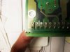
The pic with the header pin is power into the drive and the pin on the end is chassis ground that also goes through a series of caps. I am wondering if that could be causing noise in the drive and causing all this? The drive is otherwise grounded but you can clearly see there are a few pins that are fine and a few that are not.
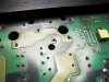
The next pic is a couple of bridge rectifiers. About 4 of the 8 joints look suspect to me. thoughts?
Without any motion commands, at times, the controller has errored out and shut down with a small jolt of motion in the suspect axis.
NOTE: I have no schematic for this and cannot get one. These are obsolete and no one in the USA will even repair it. I have to hope for a simple find...
This repair is on a CNC servo motor amplifier. The motion controller is coming back with positional errors basically telling me the controllerr has commanded motion but not getting feedback from the position detection systems. This problem IS intermittent and the servo motor and feedback loop will run fine for several minutes, then simply error out. When that happens, power is forced off to the drive so the diagnostic LEDs won't help much.
I have done the proper troubleshooting to determine the problem is in the this amplifier.
The circuit is designed with a 220VAC to DC rectifier and then variable PWM is applied to the servo motor as commanded. The feedback comes back from the servo motor via a 'resolver" (not a digital encoder), and the drive is responsible for converting the resolver signal to a 6 channel digital encoder output. Either the resolver signal is being jumbled in the drive or the encoder output is being jumbled.
Due to the intermittent issue, I feel this is most likely a minor short or broken solder joint. Upon inspection, it is obvious the amplifier has been repaired extensively before and not the best work IMO. Several, if not all HCF4066 chips have been replaced years ago, among various other components.
Upon inspection, I am finding several through pin joints that look suspect. The board is a 3 layer board.
The pic with the header pin is power into the drive and the pin on the end is chassis ground that also goes through a series of caps. I am wondering if that could be causing noise in the drive and causing all this? The drive is otherwise grounded but you can clearly see there are a few pins that are fine and a few that are not.
The next pic is a couple of bridge rectifiers. About 4 of the 8 joints look suspect to me. thoughts?
Without any motion commands, at times, the controller has errored out and shut down with a small jolt of motion in the suspect axis.
NOTE: I have no schematic for this and cannot get one. These are obsolete and no one in the USA will even repair it. I have to hope for a simple find...