Continue to Site

Welcome to our site!

Electro Tech is an online community (with over 170,000 members) who enjoy talking about and building electronic circuits, projects and gadgets. To participate you need to register. Registration is free. Click here to register now.

  • Welcome to our site! Electro Tech is an online community (with over 170,000 members) who enjoy talking about and building electronic circuits, projects and gadgets. To participate you need to register. Registration is free. Click here to register now.

Wind energy to electric energy

Status
Not open for further replies.
Hi WilliB,
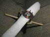
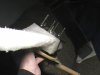
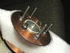
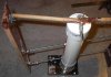
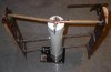
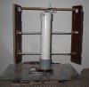
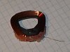
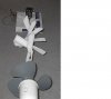
Yea the next steps I'm workin on is a copper disk to pick up the voltage then I can let the genny spin round without any wire hookups. Currently I have a stop on it so it can't get twisted but with the wind coming from all different directions it sometimes gets stuck. When I noticed a strong wind blowing I rushed out to see the meters showing 13 volts and 260 milliamps. :shock:
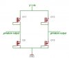
I currently looking on the net for some hall effect circuits so I make an rpm readout for it as I picked up a few effect sensors today

Cheers Bryan1 :D
 
cool ! if i find one i'll let ya know .. i was wondering what time and day it is in Austrailia ?
 
if anyone has HDPE foam (High Density Poly Ethalene) around , it makes a great tool for forming propellers..
it cuts fantasticly with a cerated knife , and can be sanded with rough sandpaper , and you can also melt the little sandings down with a lighter..
the one in the pics is 16 inches in diameter.. i just eyeballed it , and it didnt come out bad..last night i tested it from the car , it rocked !! but i couldent test the torque because it wasnt firmly connected to the shaft..it is now hopefully..https://www.artools.de/AVR/irl540n.pdf
 

Attachments

  • prop3.jpg
    prop3.jpg
    21.5 KB · Views: 1,621
  • prop2.jpg
    prop2.jpg
    22.9 KB · Views: 1,620
  • prop1.jpg
    prop1.jpg
    27.4 KB · Views: 1,633
i made a new Prop last night , this one is 32 inches in diameter..
i used a 5 1/4 disk drive frame , bearing and the plattens too..
i used two pieces each 16 inches long for the blade..
i also mounted a handel on it..
well when i tested it today *sigh* i couldent test the torque because ( in pic one ) the screw in the center kept unscrewing when i put pressure on the back of the HDD spindle .. :roll:
On the positive side it spun very well , and the blades tend not to bend backward in a heavy wind , in fact their position relative to the hub stayed the same .. it was quite windy here today so they had a fairly good test..
getting the bolt pattern was easy , as i just drilled the bolt circle from a motorcycle brake disk rotor ..
 

Attachments

  • 32_inch_prop.jpg
    32_inch_prop.jpg
    26.3 KB · Views: 1,612
  • angle.jpg
    angle.jpg
    13.8 KB · Views: 1,599
  • hub.jpg
    hub.jpg
    24 KB · Views: 1,606
wish i had a miller..
After wading through this thread I could do with a brewsky about now too :lol:
Anyways this thread has been very interesting and educational, thanks people. I'll have to give it a go soon, probably with a floppy drive motor.

Edit: Wow, I didn't realise I hadn't posted here before :shock:
 
williB said:
the answer is the forward Voltage drop on the diodes..so i googled ultra low forward voltage drop and this came up..
https://www.electro-tech-online.com/custompdfs/2005/02/PMEG1020EA_1-1.pdf
at 2 Amps these diodes have a forward voltage drop of only 460 mV !! wow..!! they have a 5 Amp version in the works
here
https://www.electro-tech-online.com/custompdfs/2005/02/mbrs320-1.pdf
is another one.. with 0.36 forward voltage drop at 3 A .. wow..

You're missing an important point. Schottkeys are good for forward voltage drop, but can suck for reverse leakage. Whereas a normal diode has a leakage in terms of microamps or less, the Schottkeys can be into the milliamp range. A fullwave bridge has double the leakage. Gets worse at elevated temps. Sometimes it doesn't matter, Schottkeys have a lot of uses. Depends on the app. In yours, if you're doing something like charging batteries, you may find the loss of a couple of milliamps the whole time the wind is not blowing may be more costly than the forward voltage of a normal diode.

There is another solution, the synchronous rectifier, which uses a driver to switch MOSFETs for extremely low losses. Vf could be just a few mV. But the circuit can be quite complicated, challenging to design, and may consume a few mA so it might as well be a few mA of Schottkey leakage loss.
 
There is another solution, the synchronous rectifier, which uses a driver to switch MOSFETs for extremely low losses. Vf could be just a few mV. But the circuit can be quite complicated, challenging to design, and may consume a few mA so it might as well be a few mA of Schottkey leakage loss.
I see nothing wrong with using another circuit to control the output , in fact i have had it in mind to use a PIC uController to eventually control the whole thing..
the pic would be connected to the anemometer to detect wind, and switch everything on..i could even have it switch on and off when the wind is blowing , say for example if my wind collector ( be it a savionous , a prop , or a cyclo turbine ) isnt big enough , then i could turn it off , for a short time , to let it build up speed , and turn it back on..
and maybe i could use the built in diode ( of a mosfet ) to my advantage..
ps i think kazakhan knew that i ment milling machine , right? :wink:
 
There seems to be a neverending list of things that you can do with old hard drives.. This is a clycloturbine . (without the tail )
It is made from a piece of 2'' OD PVC tubing , and cost about $ 6.00 to make.. I got the idea from the windstuffnow site listed in my sig..
The trick to this one is to buy the coupler & end cap pieces because the coupler gives you a very good surface to hot glue to the HD spindle , i tried it before i had the coupler , and it wobbled a little bit , but with the coupler piece it wobbles not..the end cap is where i drilled & tapped a hole for for the HD Arm , which is a critical part of the whole mechinism..
For a size reference in pic 2 at the base is an old western digital 1170 HD ..
Comming out of the tube is two 10-32 Threaded rods 14 '' Dia. which is also the length of the two air foils..
the two rods support the wieght of the foils..
at the end of the rods are door hinges which i cut with my trusty dremmel if i had to do it again i would probably buy four more of the top two Home Depot hinges.. connected to the hinges are the wood air foils ..I carved these out of poplar , which btw is excellect wood for carving it has an extreamely tight grain.. the density was consistant , in any case, with no knots!!
i got the shape off one of the propeller sites..
this is a real fun project .. in the second pic the wind would be comming from the top of the pic..in the first pic the wind would be comming from the left , slightly ahead of the turbine..that is not a optical illusion , in pic one , that is really how it looks when the ' tail ' is pointing to the side like that .. if it was turned 180 degrees you would see the carving side of the foils..
the HD Arm is screwed into the top of the end cap, and then i drilled an offset of around 0.600 '' where the wood rods are connected which actually steer the foils as it turns ( when holding offset in one spot as the foils are spinning..)
the problem i am having right now is how to balance it , i suppose i could weigh each half , but when it really gets going , it still sort of wobbles a bit..
with the fan at low speed i get 124 RPM out of it , with a nice amount of torque..
 

Attachments

  • cyclo_t3.jpg
    cyclo_t3.jpg
    66.8 KB · Views: 2,288
  • clyclo_t__2.jpg
    clyclo_t__2.jpg
    59.2 KB · Views: 2,290
  • cycloturbine.jpg
    cycloturbine.jpg
    51.2 KB · Views: 2,290
last night i made another wind anemometer , but this one is made out of a PC box fan ..
If you take out the armetures and connect it to 5V power and spin it this (below) is the output .. it has 4 negetive pulses per revolution ..
its normally high voltage is 4.323 V and its low is .322 V so it should be fun to hook it up to a PIC , i could use the comparators to count the pulses..and give me the RPMs, somehow i have to turn the RPMs into wind speed ..
 

Attachments

  • anemometer11.jpg
    anemometer11.jpg
    28.9 KB · Views: 2,231
just a few things ..
the anemometer( pc box fan ) should be the ball bearing type ..
the cycloturbine should ( and will ) be connected to a larger 5 1/4 HD..the small HD plattens bend too much..
the tuna head anemometer is still going strong .. the other day it was spinning so fast , it was a blur..
 
wow i just got 25 Volts out of this little baby..Ya'll might recognize it as a head positioning coil fron an old HD.
Then the wires broke lol :(.. and it wasnt even that close to the magnets i bet i could have gotten 30 V easy..
What is interresting is , the magnets are larger than the coil , and the wave form was a typical shape , just much larger
than i have been used to..( from one coil)
granted the .006 '' wire size couldent carry much current at all , but thats not the point.
The point is a lot of turns of wire , tightly wound in a coil , produces a lot of voltage..also i may have to rethink the way i wind my
coils the next time ..
 

Attachments

  • hd_arm.jpg
    hd_arm.jpg
    26.8 KB · Views: 2,202
I just got back to researching your Synchronous rectifier idea..
It sounds like a cool item ..

Code:
News Story

Synchronous Rectifier suits power switching applications. 

February 1, 2005 07:42 - Self-contained BERS™ NIS6111 couples high-speed comparator and MOSFET driver with power MOSFET to create diode with same forward-drop characteristics as MOSFET, eliminating heat sinks. It is capable of blocking up to 24 V and has typical forward voltage drop of 0.1 V at forward current of 20 A. Offered in 9 x 9 mm QFN package, Model NIS6111 can be used as oring diode used in servers and telecom equipment. 

http://news.thomasnet.com/fullstory/459712
 
These propellers are 11 inches in diameter..
I wanted to see if they could move the motor in pic2.. said motor has a lot of friction for them to overcome..
the thing behind the motor is my RPM Meter,( the pc box fan from a few posts back), ..hooked to the scope in the other room ..
Two prop blades would only turn the motor with the fan on high .
four prop blades , on medium speed were turning @ 241 RPM..
Six fan blades on high were spinning at 277RPM..
with no motor on there max speed was 500 rpm with one prop blade ( the third on from thr right in pic three..whicih i believe is the best shape i can come up with..as you can see they are not all identical , it took a while to come up with the best shape..i have ten more blank blocks of poly foam, which will become props..
The props are mounted to a Graphite fishing rod..
the motor is from a junk yard ,BMW , heater fan.. for such nice cars they have really crappy fan motors.. ie No ball bearings , and the current they draw is emence , from the looks of the thickness of the windings..anyway i also took out the brushes , less friction..
what i would like to do now is attach some better magnets to where the armatures are and wind some magnet wire in there .. that would be cool..
 

Attachments

  • 1props3.jpg
    1props3.jpg
    45.2 KB · Views: 2,103
  • 1props2.jpg
    1props2.jpg
    36.7 KB · Views: 2,113
  • 1props.jpg
    1props.jpg
    20.9 KB · Views: 2,105
this is what i used on the output on the test armature and it worked with a resistive load ..
by worked i mean it had a nice looking current wave ..
but i also hooked up two NiMH batteries , that didnt work as well, because the power mosfets didnt turn on as quickly as with a resistive load..
in fact just the top portion of of the center triplet was showing on the scope..picture pic 2 with the negative part inverted to make three positive going pulses..
the way my main generator works is eight single phase armatures and sixteen magnets.. so every eight of a turn is another triplet wave..
so i suppose i could ..what ?? use a zero crossing detector.. or something .. dont know..??
 

Attachments

  • one_armature_output_875.jpg
    one_armature_output_875.jpg
    9.3 KB · Views: 2,074
  • mosfet_diodes.jpg
    mosfet_diodes.jpg
    16 KB · Views: 2,083
well i tested the cycloturbine and the multiple propellers today 8)
they both worked very well , as it was very windy today..its really hard to compare them , they both have their advantages..
the cycloturbine has the advantage of being fairly compact and omni-directional..
the multi-prop has the advantage of being able to add props to it , to a point..the way i tested it was with three propellers on the front half and four on the back..so they were much more spread out than the picture above showed..and it was fairly hard to stop it when the wind was blowing , the cycloturbine was a lot easier to stop by hand , but it also has the 5 1/4 '' platten and a 2'' dia. shaft ,so it is really hard to compare them..it is so windy outside right now if the cycloturbine was out there i know it would fly apart. :lol: .my tuna head anemometer is taking a beating..
 
the nice thing about the multi prop design is its simplicity..
i also took the cyclo and the multi prop out again and both performed well, but the cyclo still needs some work, the tail which isnt pictured , is mounted on a hex screw , where the drill is in the picture.. the problem is the hole wasnt drilled perfectly perpendicular to the HD head positioning arm , so as it spins it gets tighter at one point in the rotation, and this tightness makes it wobble from the top.. sigh ..even thoogh it is centered at the base..
but the multiprop design worked flawlessly and i am going to hook a generator to it like the picture at the bottom of page 6..
 
Status
Not open for further replies.

New Articles From Microcontroller Tips

Back
Top