Continue to Site

Welcome to our site!

Electro Tech is an online community (with over 170,000 members) who enjoy talking about and building electronic circuits, projects and gadgets. To participate you need to register. Registration is free. Click here to register now.

  • Welcome to our site! Electro Tech is an online community (with over 170,000 members) who enjoy talking about and building electronic circuits, projects and gadgets. To participate you need to register. Registration is free. Click here to register now.

Will this circuit work

Status
Not open for further replies.
Did you not like post #35 .has my vote :woot:
Isn't post 35 what I replicated in post 37?
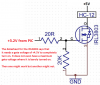
OR do I NEED the 100 ohm resistor across the HC-12? if I do then that defeats the purpose of the transistor as a switch
I need it to ONLY use current when turned on (ie when I need the HC-12 in circuit working) the rest of the time there must be no current drawn from the circuit - well that section of it anyway
 
Who says the IRL3803 Mosfet will turn on enough with a gate voltage of only +3.2V? It is spec'd with a gate voltage of +4.5V and does not even have a maximum threshold voltage listed like most Mosfets have. You cannot believe the graphs because they show a "typical" one that you cannot buy.
 

Attachments

  • Mosfet switch.png
    Mosfet switch.png
    203.6 KB · Views: 148
Lew you missed that it is a pnp transistor #35 your #37 npn
Mike's circuit will require PIC pin 16 low to switch 5v to HC12 led will be on ...
(Cannot seem to find HC12 for sale ? only eb )
 
Lew you missed that it is a pnp transistor #35 your #37 npn
Mike's circuit will require PIC pin 16 low to switch 5v to HC12 led will be on ...
(Cannot seem to find HC12 for sale ? only eb )

Whoops - my bad I was in "auto" mode

Can anyone explain exactly how the circuit works please?
I need to make sure that its not draining the battery when not needed
ie if the led is on all the time it's no use it would drain the battery

Am I right in thinking with the pin high it's turned off, the led is off, the transistor is off
With the pic pin low the diode lights, the transistor conducts and the HC-12 gets power?


I actually got my HC-12' s from Eb
I ordered them from China, takes a couple of weeks to arrive
There is someone in the UK that sells them well a couple of people but the price is like 3 times as expensive and the China supplier sends them out in pairs
you need a pair to work anyway


**broken link removed**
 
Lew It seem to take a time for ETO in USA to catch up , your last #44 looks ok , should work as required , Mike's post 35, explains with I presume a simulation , pin 16 at 3.3v ( or 3 state , input ) holds off led and pnp base , at ~2v at pin 16 , current flows in base , led glows transistor turns on , 5v available for HC12, bytes move !
Edit Led needs to have a 2v forward voltage ( red )
 
I'm rather late to the party, but going back to Mike's circuit (#4) you can get transistors which have a NPN and a PNP in one package, so you could do a fully bipolar version of #4 and still keep the component count down. You may get lower power consumption than the LED circuit - would have to calculate.
 
I don't get the "sinking current and sourcing"

Sinking is switching the bottom, sourcing is switching the top - as explained in my tutorials - the one you want is the two transistor version two pictures down from the one you posted.

but
Hopefully this will work?

Again, it's a poor choice, as it's NOT a switch - aside from other problems :D.
 
Lew247,

Going back to your original idea, but putting the load in the collector leg and assuming that the HC-16 is pulling less that 100mA:
upload_2016-3-24_14-6-39.png

and assuming that the 5V on Pin 16 is the same 5VDC Vdd as from the PIC PS,
a sim of, essentially, your first circuit:
No sig to NPN:
upload_2016-3-24_15-13-7.png

Sig to NPN:
upload_2016-3-24_15-31-57.png

Note the 4.7k resistor: with a loss of Sig from PIN 16, this will pull the NPN base to GND, shutting it OFF .

I may have PINs 15 and 16 reversed as to function. But, as you can see, the circuit functions just fine as a switch, with minimal current draw (≈5nA), when quiescent.
 
Lew , I think the (MikeM) circuit on #44 is 'elegant' it has the led indicator, and is on the high side , so the TX from the HC12 cannot try to power the PIC RX pin, even during PIC reset power up (all ports are inputs) the HC12 5v will not be active. bread board it see how it is in real life...
 
granddad is right.

And yes, the PIC pin 16 has to go LOW for the circuit to work.
upload_2016-3-24_19-43-15.png


upload_2016-3-24_19-42-34.png
 
granddad is right.

And yes, the PIC pin 16 has to go LOW for the circuit to work.
...

Cowboy lowered the resistor between the LED cathode and the pic port from 680Ω to 100Ω. I specifically selected that resistor to provide sufficient base current to saturate the PNP. Lowering it just wastes power without much benefit.
 
Lew Don't want to upset your apple cart .... there are 5v regulators with a shutdown pin . NCV4266 as example...
I ordered 2 HC12 from bangood to 'play' with see if i can extend the range of my PIC24 greenhouse environment monitor , thanks for info.
 
...I ordered 2 HC12 from bangood to 'play' with ...

I'm confused. Do you talk to the HC-12 using it as a PnP USB device, or is the communication to its Rx/Tx pins just RS232 serial?
 
Status
Not open for further replies.

New Articles From Microcontroller Tips

Back
Top