Electro Tech is an online community (with over 170,000 members) who enjoy talking about and building electronic circuits, projects and gadgets. To participate you need to register. Registration is free. Click here to register now.
Welcome to our site! Electro Tech is an online community (with over 170,000 members) who enjoy talking about and building electronic circuits, projects and gadgets. To participate you need to register. Registration is free. Click here to register now.
A Wien bridge that has equal parts values has a loss of 3 times. Then the amplifier circuit must have a gain of slightly more than 3 and the automatic-gain-control reduces the gain to exactly 3.0.
after the wien bridge oscillator, i wanted the output to be phase-shifted, i try to use a series RC circuit, can anyone tell me how to calculate the shift? what equation to use?
after the phase shifting, i need to output it as a soundwave through a speaker.
my supervisor told me to put a power amplifier between the speaker and the oscillator. he said power amplifier is an IC chip. Can any1 suggest a circuit for me? Internet have too many until i dont know which 1 is suitable. i think i need to use a 25W speaker.
When the reactance of the capacitor equals the value of the resistor then the phase shift is 45 degrees if the load resistance is very high.
Why do you want a phase shift?
A continuous tone into a speaker at 25W will blow your head off. Music playing with the peak power at 25W has an average power of 1W to 2.5W.
There are many amplifier ICs made for car radios. A TDA2003 has an output of 1.7W into an 8 ohm speaker at low distortion with a 12V supply.
Its output is 12W into a 1.6 ohm speaker at low distortion with a 16V supply.
oops mistake....is 0.25W...the printing is not clear. sorry.
erm...actually i'm doing a beamforming project. So i need about 4 of the same audio output but with changable phase shift, in order for the sound to change direction depending on how much phase shifting is happen to the 4 audio output. i need an equation to make sure the shifting done is accurate..
hope can show me a website or tutorial side on this........phase shift calculation
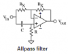
An adjustable allpass network can make a pretty good adjustable phase shifter at a single frequency. Adjustable delay over a wide frequency range (like the audio spectrum) is much tougher, but I don't think that's what he needs.
EDIT: AG posted while I was composing.
Swapping R and C will give 0 to -180 degrees range. As shown, you'll get 180 to zero degrees range.
Hi Ron,
I disagree. A allpass filter shifts the phase from 0 degrees to 180 degrees.
At high frequencies the capacitor is a short so the circuit is a buffer with 0 degrees phase shift.
At low frequencies the capacitor has no effect so the circuit inverts with 180 degrees of phase shift.
At frequencies in between then there is about 90 degrees of phase shift.
You may not have read my post after I edited it. My original post had some errors. My only point is that you can make the circuit inverting or noninverting at ~DC, and opposite at high frequencies, depending on the positions of R and C.
hmm... i got this LM386 IC for power amplifier circuit to drive my loudspeaker..
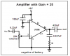
From the datasheet, i can see the circuit with 20 gain. I juz wanted to confirm does the output from my wien bridge oscillator is the direct input to the pin 3 of the IC such as the circuit shown?
Mneary: sorry, my theory is very weak, explain more?
Your oscillator has an output voltage of about 2V peak-to-peak. If it directly feeds an amplifier with a gain of 20 then the output will try to be 40V peak-to-peak. The max output voltage of an LM386 amplifier that has a 9v battery is 6v peak-to-peak so the output will be extremely distorted into a aquare-wave.
Use a volume control in between to reduce the output level so the LM386 does not clip the signal. A coupling capacitor must feed the volume control.
if i'm not using battery, but using DC supply or 9V to the LM386. Is it applicable.
plus i tried audioguru cirucit, i can only get my output till after the 0.33uF capacitor. After the 20kohm ressitor, i cant get any waveform at all....wat is wrong?
It is clipping and it has a highpass filter feeding a load.
The clipping will cause the top and bottom of the wavform to be flat.
The highpass filter causes the flat top and bottom to be curved and shifted on a diagonal toward the right side.
What is its load?
Measure the output without a load and the clipped top and bottom will be flat.
I got 1 big problem here, for wien bridge the eqn F= 1/2pixRxC is a fixed eqn for the rc tuning circuit rite?
but y my circuit only allow 1nF and 40Kohm to generate 4kHz freq but when i change to use 0.1uF and 400ohm, the oscillator does not oscillates with 4kHz?
9V from a 9V battery is exactly the same as 9V from a power supply.
The 0V (ground) of the oscillator must be connected to the 0V (ground) of the LM386 amplifier.
i tried audioguru cirucit, i can only get my output till after the 0.33uF capacitor. After the 20kohm ressitor, i cant get any waveform at all....wat is wrong?
There is no 20k resistor in the LM386 circuit. There is a 20k volume control that can be turned to give from nothing up to the full signal from the oscillator to pin 3 input of the LM386.
If the volume control has an audio taper (logarithmic) then it will work best when set to about half-rotation.
when i change to use 0.1uF and 400ohm, the oscillator does not oscillates with 4kHz?
Look at the datasheet for any opamp. Its minimum load is 2k ohms. 400 ohms is much too low.
For 4kHz use two 0.01uF capacitors with two 3.9k resistors.
For audioguru's circuit, if i need to vary the gain, what should i do with the circuit? Ex. a potentiometer ??
Ground 0V from the oscillator, do audioguru refer to the circuit i use, or the circuit audioguru suggested? because i'm using my circuit for the wien-bridge, and i finally get a beautiful sinewave.
I now stuck at whereby i had constructed the circuit as as shown by audioguru for the amplifier, the only place differ is the 10ohm resistor where i replace wif 27ohm because i cant find any 10ohm around.
I take the output from pin6 of the oscillator and connected to the 0.33uF and i didnt see any outputs.
And i still trying on the phase shifting of the output by using Series RC circuit, as i try with a Rvar = 250k potentiometer and C = 1nF/0.1uF ceramic capacitor, the output doesnt shift as i predicted eventhough i rotate the potentiometer from 0ohm to 250ohm. i wondered why?
The LM386 amplifier doesn't work unless the 0V of the oscillator circuit is connected to the 0V of the LM386 circuit.
I now stuck at whereby i had constructed the circuit as as shown by audioguru for the amplifier, the only place differ is the 10ohm resistor where i replace wif 27ohm because i cant find any 10ohm around.
Are the 0V connected together/
Is the volume control wired properly?
Is there a 6V to 9V supply for the LM386?
And i still trying on the phase shifting of the output by using Series RC circuit, as i try with a Rvar = 250k potentiometer and C = 1nF/0.1uF ceramic capacitor, the output doesnt shift as i predicted eventhough i rotate the potentiometer from 0ohm to 250ohm. i wondered why?
An allpass filter circuit shifts the phase well without attenuation. A series RC is only an attenuator.
A series resistor feeding a capacitor to ground is a simple lowpass filter that shifts the phase and is also an attenuator.
This site uses cookies to help personalise content, tailor your experience and to keep you logged in if you register.
By continuing to use this site, you are consenting to our use of cookies.