Continue to Site

Welcome to our site!

Electro Tech is an online community (with over 170,000 members) who enjoy talking about and building electronic circuits, projects and gadgets. To participate you need to register. Registration is free. Click here to register now.

  • Welcome to our site! Electro Tech is an online community (with over 170,000 members) who enjoy talking about and building electronic circuits, projects and gadgets. To participate you need to register. Registration is free. Click here to register now.

Why Opamp with potentiometer?

Status
Not open for further replies.
Hi,

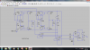
With 1v out of the left buffer and 0v out of the right buffer, the current out of the first buffer is 1/(1k+1k) which equals 1/2000 amps, and that gets 'mirrored' into the 1k resistor so that produces 0.5v at node n009 right?

You should try to understand these circuits using DC first then AC later. They are DC coupled so you can understand a lot just by using DC.
 
The thing that I don't understand is how it gets mirrored into 1k resistors? 1/2 mA is the current that goes through both 1k s at the output of first buffers, right? then after that how it gets mirrored into 1k resistors at the output of current mirror?
 
If I add rest of circuit I mean the last op amp and 2 voltage buffers (below picture). The very last output voltage should be 5v because at the current mirror section I get 0.5 v and at the output stage I get 10v then the overall gain is 5v while the simulation result shows 1v at the final output with 0.1v input. ( I had to decrease the voltage of input to 0.1v because in simulation with 1v in the output becomes saturated.)
 

Attachments

  • Untitled.png
    Untitled.png
    124.2 KB · Views: 208
  • Untitled1.png
    Untitled1.png
    119.6 KB · Views: 192
You should try to understand these circuits using DC first then AC later. They are DC coupled so you can understand a lot just by using DC.

I applied 1v DC to left op amp and got 2.2 mA goes through 1k resistor. Shouldn't I get 0.5 mA here?
 
Hi,

Let me ask you a question first...
Do you understand basic circuit analysis, such as Nodal Analysis or something like that? Most of your questions involve looking at the circuit and calculating some voltage or current, and it would help a lot if you understood basic analysis a bit better.

With 1v into the left buffer, we get 1v out. With 0v into the right buffer, we get 0v out.
If we have two 1k resistors in series connected across the output of these two buffers, we must get (1-0)/2000 amps out. That's 0.5ma. If not, then something is really wrong. That's when you start checking voltages and connections and simple things like that.
See if you can find something simple wrong.

The simplest explanation of a current mirror is that it is a "current controlled curent source" that puts out the same current as it gets into it, so it's got a current gain of 1. So the output current is the same as the input current, as long as it is held within some limits such as output voltage and temperature gradient and stuff like that.
So a current controlled current source with a gain of 1. Current flowing DOWN in the left side will also flow DOWN in the right side.
A little more complex explanation is that the input transistor gets a current, and because it acts like a diode that particular current results in a particular voltage across it. That same voltage is then applied to the other transistor, and because that transistor now has the same base emitter voltage, when the collector is at the same voltage as the first transistor the current in the second transistor has to be the same as it acts in 'reverse' of the first transistor. If the second transistor collector voltage is not the same as the first (as is often the case) then the second transistor does not mirror the current *exactly*, but there will be a small error due to the Early effect. The four transistor current mirror attempts to make up for this effect, but because it is small you may not have to worry about it at least not until you get everything working right the way it is now with the simpler circuit. There are other errors too but we dont worry about them right now.
So you see it gets more complicated, but thinking about it in terms of a current controlled current source with a gain of 1 should suffice for now: "whatever current goes in one side comes out the other side".
 
I think there is a problem in one of your posts (#134). Please correct me if I'm wrong.

This is what you said:

"Part 2: there are the two 10k resistors on the output of the input buffers. With 1v in (and 1v out) we get 1/10000 amps through the 10k With 2v in we get 2/10000 amps through the 10k."

"Part 4:
We have a 1k resistor on the output of each current mirror. With 1ma through 1k we see 1v across that 1k. With 1v in we get 1/10000 amp out so we only see 0.1v across the 1k, so the voltage gain from input to the output of the current mirror is 1/10."

As you can see this is totally different from what you said about 1k resistors on the output of input buffers. In post #134 You said with 1v out of the second buffer and 0v out of the first buffer (circuit configuration attached in post #133 which is similar to the circuit we talked about in recent posts) and 10k resistors at the output of input buffers we got (1-0)/10k current through 10k resistors while in your recent post you say with 1v out of the left buffer and 0v out of right buffer and 1k resistors on the output of input buffers we got (1-0)/(1k+1k) amps through 1k resistors. I think we get 1/20000 amp (you said 1/10000 amps) through 10k resistors and with 1k at the output of current mirror we have 1/20 v at the output of current mirror not 0.1v that you mentioned in post #134.
 
Last edited:
Hello,

Yeah, at some point you have to try to understand some of this simple analysis yourself.
I talk about this because without some basic background in analysis you'll always find more advanced circuits extremely difficult and have questions that go on forever.

You had changed the circuit from having resistors on the output of the op amps going to ground to resistors that connected together instead. I was talking about the circuit where the resistors go to ground.
When the resistors go to ground, any output voltage causes a current to flow through the resistor based on the simple Ohm's Law which says we have I=V/R. When the resistors are connected together we only get half that current unless we also halve the resistance. Using 1k on each output to ground gives us 1ma per volt, while using two 1k in series across both outputs only gives us 0.5ma per volt. You will notice however that the other buffer also puts out current, and that causes the output of that current mirror to have the opposite polarity voltage, so if one section has 0.5v then the other section has -0.5v (with 1v input on one channel only) and that goes to the output stage which means the output stage sees a total differential of 1v.
This is what i mean by simple analysis.

Perhaps we should back up and go over some basic circuit theory? What circuit theory have you had so far?
 
Last edited:
in post #134 you talked about the circuit that the resistors on the output of input buffers are grounded, right?

I thought you were talking about the circuit that I attached to post #133 which resistors on the output of input buffers are in series. That's why I thought there was a problem in your post.

I saw in different LTspice simulation results that the polarity voltage of current mirrors are against each other. Let's assume 1v is applied to the left op amp (like circuit in post#340). you said in previous post "the other buffer which one of its input terminals is grounded puts out current". This current is only because of the current that transistors in current mirror produce, right? if the the answer is right then why this current causes the output of that current mirror to have the negative polarity voltage?
 
Last edited:
Hello,

With the two 1k resistors in series (not to ground) and on the output of the buffers, one buffer puts out 1v and the other buffer puts out 0v. Since the two resistors are connected to both outputs but only one is high, the current flows OUT of the left buffer output and IN to the output of the right buffer. Thus, the right buffer is sinking current so it sees a negative current while the left buffer sees a positive current.
Again this is basic circuit analysis.
 
Yeah you are right that is basic circuit analysis but After asking my question here, I thought about it more and found out why voltage node of current mirror outputs are against each other but I forgot to come back here and edit that part of my post. Sorry about that.
 
Hi,

No problem, but what have you done in the past, like any kind of circuit analysis, even Ohm's Law?

It helps to take a good long look at the situation in the circuit, then ask yourself how this can happen. Sometimes it's something simple.

Very interesting circuit though. And the link was good too, thanks for posting that.
 
Many, many years ago (like 45) there was a similar circuit to boost the GBW product and drive of the uA709 opamp. But the uA709 was an incredibly primitive opamp, why are you doing that with a TL084?
And following that with yet another TL084? What is the point?

And one of the reasons you may not be able to zero the offset is, that the power supply current draw in an early JFET opamp like the TL084 may not be symmetrical from the V+ to the V- terminals.

Hi,

I was assuming that we would find a way around this or other offset problems, but havent given it any thought at all yet.
 
ooooooooooops! I hadn't noticed that this thread is over 350 messages long. My comment may not apply, as I only saw the circuit in the early posts.
 
Finally I could get the the gain of 10 from the circuit by changing the resistors at the first stage (before and after current mirrors ). In one of my test I had a strange result that I attached to this post. I input 0.5v to one of input buffers the other input buffer is grounded. I got output voltage with the peak of 5v. Voltages at the output mirrors were correct but I don't know what happens at the output stage that I got the positive peak of voltage(5v) like in picture? with 0.5v input I have 2v at the input of last stage (1v at the output of one of mirror and -1v at the output of the other one (n18 and n20)). It seems that Output stage can't amplify difference voltage of 2v with supply voltage of 15v and -15v.
 

Attachments

  • Untitled.png
    Untitled.png
    23.6 KB · Views: 194
  • 2.jpg
    2.jpg
    171.9 KB · Views: 209
Hello,

That sounds about right because if we had a 2v input to an op amp stage that had a gain of 10, it would want to amplify that up to 20v, and with only a +15v supply the output would clip. I would expect a -2v input would clip the negative peaks too with a negative rail of only -15v.
 
I agree with you I don't find any reason for why negative peak of output voltage wouldn't be clipped with supply voltage of -15v. By the way I should increase the voltage of supply voltage to 20v for example. Is it possible for 741 to have +20v and -20v as supply voltages?
 
Last edited:
Hi,

Your scope pic does not show the vertical nor the horizontal units. That makes it impossible to interpret. Try to show the grad units on the pics so we can tell what we are looking at. This has to be done AT THE TIME of the measurement, not later.


Some 741's are limited to plus and minus 18 volts, while others are limited to plus and minus 22 volts. You'll have to check the data sheet FROM THE MANUFACTURER that actually made the part. Not all LM741's are the same.
 
The vertical unit is volt and horizontal axis shows time. Also The volts/div setting for output voltage is 5 volts. The setting of input voltage is 2 volts/div.
 
Last edited:
Hi,

I think you mean 5v per minor div and 2v per minor div right?
Well then the scope calibration is got to be way off. The negative peak goes all the way down to -25v, which would not be possible unless there were capacitors on the output of the op amp with a -15v power supply.
 
Status
Not open for further replies.

Latest threads

Back
Top