Continue to Site

Welcome to our site!

Electro Tech is an online community (with over 170,000 members) who enjoy talking about and building electronic circuits, projects and gadgets. To participate you need to register. Registration is free. Click here to register now.

  • Welcome to our site! Electro Tech is an online community (with over 170,000 members) who enjoy talking about and building electronic circuits, projects and gadgets. To participate you need to register. Registration is free. Click here to register now.

Why Opamp with potentiometer?

Status
Not open for further replies.
Well then explain why this "untitled2.png" pic is different than the one you posted in post #233?
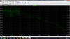
In post 233 presumably you have the circuit that measures CMRR, and it does not go negative until after 1MHz or thereabouts.

You mean you are getting a bad result for this more advanced circuit?
 
The result in post number 233 is related to the circuit which is attached to post #233.

Yes I mean for an advanced circuit I'm getting a bad result
 
Hi,

Something, somewhere is not working correctly. I have not determined what it is yet.

Forget about CMRR for a minute, just try to get an output from one of the op amps that is being driven with a 1v ac source. The input reads "0db" which is correct, but the output reads "-36db" which is way way off. So the LM358 is not even amplifying the signal at even 10Hz. That means something is very wrong.
I even set the power supply DIRECTLY to the power supply terminals of the LM358, and do not get good results (this bypasses the current mirrors for that section).

This problem might be related to LT Spice itself because if i erase all of the op amps and associated resistors and transistors for all but one op amp, the op amps starts working normally again showing the right output.
For 1vac input and a buffer it should show 1vac output which will show up as 0db on the output. That works ok with one op amp, but with the whole circuit intact it does not work, showing something like -36db.
We'd have to find a work around or else abandon LT Spice.
We could have drawn something wrong like a label or something, but it doesnt look like that so far.

I have now tried the LT1001 op amp and find the same problem. Plotting the AC output of one op amp shows -20db when it should be much higher.
Whoops, scratch that, you had the input set to 0.1 vac instead of 1vac that we had been using all along. So the LT1001 op amp model seems to be ok for this while the LM358 model does not seem to be ok at all. Perhaps we can find an LT op amp that is similar to the LM358 and use that instead for the tests (again keeping in mind this is all still academic).
 
Last edited:
LT1001 doesn't work well in transient analysis. It gives me gain of 8 v instead of 10v at the very last output when I input 2 different SINE voltage sources (for example 2v to one channel and 1v to the other one).
 
Hi,

What i suspect is happening is the internal numerical accuracy becomes a problem when the number of nodes goes up. It depends on other things too, but in general the more connections the bigger the matrixes will be and then the internal numerical resolution becomes a problem.
For example, if we have a resolution of 4 digits and we compute and store two numbers 1.010 and 1.020, when we subtract 1.020-1.010 we get 0.010, and that result would most likely be used for something else maybe even a derivative. Similarly, if we have 1.002-1.001 we get at least some usable results 0.001, but what if the two computations left us with 1.0002 and 1.0001, since we only have 4 digits in our example system these would store as 1.000 and 1.000, and subtracting we get 0.000 which is nothing useful. If it was used as a derivative it might return a slope of zero instead of a slope of 0.00001, and a slope of zero would tell us the node did not change anymore even though in real life it did and we need that for the next computation.

This happens pretty fast with some algorithms too, even good ones. We a regular matrix doing plain old simultaneous equations sometimes we cant even get a 9x9 matrix to return good results using 16 digit arithmetic.

The LM358 model may be more complex than the LT1001 model so it may be using more nodes. We might be able to create our own model that works similar to the LM358 but uses less nodes. I think i have one around somewhere that i made up many years ago so i'll have to see if i can find it.

But one thing to always remember though is that any model is limited as to how well it will show the true CMRR anyway. Maybe it's just not worthwhile to do anyway unless you just want to study the effects of different component variations on the CMRR based on the original CMRR without changing anything.
 
I did a little test on the differential part of this circuit with both LM358 and LT1001. In transient analysis I measured voltage of node 009 (output of first current mirror). when I use LM358 the voltage of n009 is more reasonable than LT1001. With LT1001 I have a voltage shift in this node and don't know this is because of internal numerical accuracy or something else. I attached the result and .asc file to see better what's going on.

Untilted 3 is for LM358 and Untitled 4 for LT1001
 

Attachments

  • Untitled3.jpg
    Untitled3.jpg
    216.4 KB · Views: 167
  • Untitled4.jpg
    Untitled4.jpg
    220.3 KB · Views: 165
  • Draft3.asc
    5 KB · Views: 168
Last edited:
Hi,

Ok then i guess we are seeing some peculiarities of the LT Spice program with some models.
For certain resistor values and limited frequency range we should see very similar results for both op amps, except when looking at the finer details like offset and gain bandwidth and stuff like that.
 
With LM358 I have a negative CMRR! With LT1001 diffrential gain is 8v instead of 10v! So it's better to use LT1001 for measuring CMRR and LM358 for calculating gain in LT spice software in order not to see these strange results.

One more thing when I use LT1001. In CMRR plot (below picture), there is irregularity from 1Hz untill 100hz. what causes irregularity? It seems that in common mode gain there is this kind of irregulartiy too.
 

Attachments

  • Untitled.png
    Untitled.png
    148 KB · Views: 148
Hi,

As i said before, the numerical stability comes into question and from that plot we see what looks like the effects of limited precision numerical computation and storage capability.. The resolution makes the graph bounce up and down because some storage values are not possible, and yet the calculation comes up with a slightly different result each time so we see it bounce between the possible values because it can not store anything in between those two extremes.

For example, if we only had 4 digit math with a resolution of 0.004 and the first calculation gave us 1.003 and the second gave us 1.001, it might display this as 1.004 and 1.000, which could look like a big jump if we zoomed in, and furthermore it might jump back and forth between values because the next calculation is based not on the true values (1.003 and 1.001) but on the stored values 1.004 and 1.000. So one is too high and one is too low so it skews the calculations that follow too, and each calculation has to deal with a value that is too high or too low and so it never stabilizes to the true value.

I could show you some simple example of this using matrixes but it gets a little complicated to show on the web. Once you get past a certain matrix order with a given limited precision the numerical stability gets bad as well as the accuracy.
An example could be trying to fit an 8th or 9th order polynomial to some data points using the normal 16 digit precision used natively on most modern computers. With a range of something like -1e302 to +1e302 you'd think we could do anything, but nope, the resolution of the stored results is what messes everything up, and it gets really bad sometimes.

What does surprise me though is that LT Spice seems to have no way to deal with or at least report this. Did you look at the "Error Report"? Maybe that will have some note in there.
I searched the web but could not find anything on the numerical limitations of LT Spice. All i found was what appears to be a statement that it has no limitation on the number of nodes. That's not quite enough information though.
 
I couldn't find anything about " Error Report" in LTspice too. Besides I found nothing on numerical limitations. It seems no one has this kind of problem. I would keep searching, hope to find something related to this issue.

In all around different websites they said: " email bug reports to LTspice@linear.com" :D
 
With very high CMRR values the CM gain is correspondingly very small. So noise, if modelled correctly, will have a correspondingly large effect. Perhaps that is what you're seeing.
As for the differential gain being not as expected, have you taken into account the R2 and R10 resistors which have a major effect on gain?
 
I couldn't find anything about " Error Report" in LTspice too. Besides I found nothing on numerical limitations. It seems no one has this kind of problem. I would keep searching, hope to find something related to this issue.

In all around different websites they said: " email bug reports to LTspice@linear.com" :D

Hi,

Actually it is the Spice Error Log. I checked it though and all it seems to indicate is that it has trouble finding the operating point.
It works faster with ".option noopiter" anyway so i tried that but it did not solve the problem where the LM358 does not act as an amplifier anymore.

As a simple experiment, i gave the right hand circuit its own plus and minus 15v supply, and gave it its own input sine source. I then changed he left hand side circuit sources to 0v. One of the LM358 op amps then started to work normally again.
So when some of the components are taken out of the circuit, even if that circuit is not connected to the circuit being tested, the spice program starts to show the correct results again. That must mean there are limitations that we cant see just yet.

To test this yourself just view the output of one of the LM358's with a node label. Give each circuit its own supplies and input source. Ground each side supplies in turn while you test the other side, and test without grounding any supply voltages. Big difference between grounding one circuit and not grounding one circuit, when there should be no difference at all (testing only one circuit op amp output, that's all).

There is a workaround but it's not easy. Curve fit the CM output and then use the resulting function in the graph display entering that function instead of the usual V(cm).
So say we use a second order curve fit, we'd end up with something like:
vcm=A*f^2+B*f+C

so instead of using:
V(diff)/V(cm)

we'd use:

V(diff)/(A*f^2+B*f+C)

Alternately just do three points and do the extra math by hand (ground out one side at a time to get the diff and cm):
diff1/cm1
diff2/cm2
diff3/cm3

That would probably be good enough for most purposes. Not an entire graph of CMRR vs frequency, but probably good enough to get an idea what is going on.
 
Last edited:
Actually it is the Spice Error Log. I checked it though and all it seems to indicate is that it has trouble finding the operating point.
It works faster with ".option noopiter" anyway so i tried that but it did not solve the problem where the LM358 does not act as an amplifier anymore.

Sorry I don't understand you. You mean when we use LM358 and measure CMRR of this circuit, operating point wouldn't be found even with ".option noopiter" and in some cases LM358 doesn't act as an amplifier?

I have a question. When we use LT1001 we get a CMRR around 270 db. Is there a potential this result would also be wrong? In fact can we surely say CMRR of this circuit is 270db in a range of frequency?


As a simple experiment, i gave the right hand circuit its own plus and minus 15v supply, and gave it its own input sine source. I then changed he left hand side circuit sources to 0v. One of the LM358 op amps then started to work normally again.
So when some of the components are taken out of the circuit, even if that circuit is not connected to the circuit being tested, the spice program starts to show the correct results again. That must mean there are limitations that we cant see just yet.

Actually in this condition you are simulating only one circuit, right? we did this test with LM358 before when we calculated differential gain and we had a correct result. we have had wrong results with LM358 since we tried to draw both circuits(differential and common mode) in one schematic.
 
Last edited:
Hi,

No the operating point is found using a different method then.

To understand the CMRR you'd have to study the model to find out how they are doing it and maybe why they do it that way. This might be based on what the manufacturer knows about the internal construction of the op amp as to the differences in die areas that can occur.

If the circuit works when we only use one circuit instead of two, then that would be the key to getting any results. Do one part at a time and divide manually for only a certain few points.

We could create a model with infinite CMRR but it would probably show up as 300db or something like that. I've never tried this, but an amplifier with perfectly balanced inputs would have infinite CMRR yet the simulator would have to come up with a finite number somehow or else flag an error.
 
I would try to get CMRR of this circuit when I assemble it on a breadboard. but I don't have any sweep generator. I can get common mode and differential gain but I don't know in what frequency I measure them. I mean when i have no sweep generator What extra component can add to circuit to help me change the frequency?
 
Last edited:
What extra component could I add to circuit to help me change the frequency?
In the LTS 'Special functions' folder you'll find 'modulate'. That can provide frequency sweeps.
 
To alec_t: I mean in real life breadboard circuit not in LT spice program. I want to assemble this circuit on breadboard but I don't have any sweep generator to change the frequency.
 
Last edited:
I don't have any sweep generator to change the frequency
What is your signal source?
 
Hi,

Dont you have a frequency generator of some type? Even if it does not sweep, you can take the readings at several frequencies like 1,10,100,1000,10k, 100k or to be more thorough at frequencies:
1,2,5,10,20,50,100,200,500,1k,2k,5k,10k,20k,50k,100k,200k,500k Hertz
which is roughly a log scale.
So you dont really need a sweep, you can do it manually, just change the frequency and take another reading of whatever you need. If you read vdiff and vcm then you can divide with a calculator.

If you do not have any generator then you will have to either buy one or build one yourself.
 
I assembled a simple amplifier with 741 op amp on breadboard - circuit's schematic has been attached below- and test it. In real world I got almost 45db from 1Hz untill 100hz. the result that I got is different from CMRR in datasheet. In datasheet CMRR is 90db. in fact There is a big difference between the CMRR that I have and CMRR in datasheet. This difference would be reasonable or not?
 

Attachments

  • Untitled.png
    Untitled.png
    12.3 KB · Views: 153
  • Untitled1.png
    Untitled1.png
    43.2 KB · Views: 144
Status
Not open for further replies.

New Articles From Microcontroller Tips

Back
Top