I'm struggling help please!
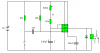
Looked on RS and Maplin and can find little 120uF which is needed for my 555 timer circuit other than low spec alloy, which I read isn't recomended for timer circuits as this circuit needs to be stable over time.
Can anyone suggest a suitable supplier for a good and stable 120uF cap for attached circuit?
Also, while on the subject I just got a basic 10mm trimmer for the Pot, it's vital that once the pot is set the circuit doesn't 'drift' much over time do I need any special kind of pot or is a normal trimmer, used once to set the time value going to be good at sitting there and not playing up/altering resistance?
Greg.
")
