Continue to Site

Welcome to our site!

Electro Tech is an online community (with over 170,000 members) who enjoy talking about and building electronic circuits, projects and gadgets. To participate you need to register. Registration is free. Click here to register now.

  • Welcome to our site! Electro Tech is an online community (with over 170,000 members) who enjoy talking about and building electronic circuits, projects and gadgets. To participate you need to register. Registration is free. Click here to register now.

Where to find - Futaba BJ100GK / VSL0276-B display

Status
Not open for further replies.

Exie

New Member
Hi Folks,

Following my last successfull repair job, I thought I might pull out the VCR and see if I can work out why the display blanked out a while back. It still works fine, just no display on the front.

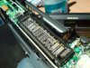
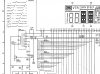
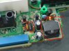
So I downloaded the service manual, and got it all dissasembled, the screen seems to be made of a thick glass piece (LCD?), there is no LED or Globes I could find that might be responsible for illuminating the display. As I inspected the unit, I noticed a large black spot in the lower right corner, so I think the screen piece is stuffed.

On the back of the screen it has a sticker "Futaba BJ100GK / P.N. VSL0276-B"

Any idea where I could source one of these ? I suspect it's a pretty old part, as its a pretty old VCR, am I wasting my time ?
 

Attachments

  • DSC00131-sml.JPG
    DSC00131-sml.JPG
    152.7 KB · Views: 1,078
It's basically a valve, it's called a Vacuum Flourescent Display (VFD), it doesn't have a back light (like an LCD) it generates the light per segment inside. Because it's a valve it needs a heater supply (these are usually the outer pins, with the outer two on each side being the same). They require a heater supply of two or three volts, which needs to be floating, so is often AC and capacitor coupled. They also require reasonably high feed voltages, and usually have both negative and positive ones.

On some VCR's these are all supplied directly from the mains transformer, but some use a little inverter to feed them all - these are usually made by TDK (the tape people) and are a small screened box - this is what usually fails, or the heater coupling capacitors if it uses them. It would be EXTREMELY rare for the display to fail, apart from the normal lack of brightness as they age.
 
Wow! Thanks for the tips. I have the schematic here, and I can see what you mean about the +ive and -ive lines to power the display. The diagram (which I dont understand much of) shows something that might be the inverter you mentioned.

It's past 2am here, so I might give it a miss until tomorrow. I'll pull out the multimeter and have a poke around then. Maybe a replacement inverter would be easier to source than the VFD ?
 
Exie said:
Wow! Thanks for the tips. I have the schematic here, and I can see what you mean about the +ive and -ive lines to power the display. The diagram (which I dont understand much of) shows something that might be the inverter you mentioned.

Just follow the supplies back from the VFD.

It's past 2am here, so I might give it a miss until tomorrow. I'll pull out the multimeter and have a poke around then. Maybe a replacement inverter would be easier to source than the VFD ?

Probably easier, but you might even be able to mend the inverter - there's a little PCB inside the can.
 
Thanks Nigel,

I've tested for any power going to the VFD, and your correct, theres nothing.

I've checked out the schematic, and it looks like the power comes from a little transformer labelled as an ETE13K60AY which is a panasonic part (it's a panasonic VCR).

I've located the part on the board, and its a sealed unit, which from eye sight, looks ok. I did notice a little black transistor, and it has dark brown markings on the PCB, looking at the diagram, it's component Q1701 - Panasonic 2SD937A

It's a bit hard to power up, and get a multimeter onto it (without touching other things and blowing myself up), do you think it's a fair bet that the transistor could be broken, stopping the power to the VFD ?

I'll attach a snapshot of the diagram, which might mean more to people on here than it does to me.

p.s. Apologies if this is getting off-topic. Happy to start another thread if the moderators prefer.
 

Attachments

  • diagram1.jpg
    diagram1.jpg
    171.3 KB · Views: 955
  • DSC00134-sml.JPG
    DSC00134-sml.JPG
    55.7 KB · Views: 1,076
Yes, the transistor has probably failed, although something might have killed it, this is essentially what's inside the TDK modules, obviously Panasonic have built their own on the board. There's a small choke feeding power to the inverter, if the transistor has gone short that will probably be O/C.
 
Nigel Goodwin said:
There's a small choke feeding power to the inverter, if the transistor has gone short that will probably be O/C.
Sorry to sound a bit "thick" but I dont understand what your saying here....
"choke" ? I've got some capacitors, resistors and a diode surrounding the transistor.
"O/C" ? as in .. Over Clocked ?! Out of Control ?

p.s. Dont laugh, but I read somewhere that transistors were somewhat interchangable, I found the spec sheet for the Panasonic part (2SD973A), and wondered if a local **broken link removed** might work in its place. If so, I could pick one up tomorrow morning from the local electronics store. Should I replace anything else whilst I'm at it ? I expect the transformer will be hard to get, so I'm crossing my fingures hoping it's ok.
 
Exie said:
Sorry to sound a bit "thick" but I dont understand what your saying here....
"choke" ? I've got some capacitors, resistors and a diode surrounding the transistor.

A choke is an inductor, it's feeding the power to the input of the transformer.

"O/C" ? as in .. Over Clocked ?! Out of Control ?

Open Circuit - a VERY common electrical term! (S/C is Short Circuit).

p.s. Dont laugh, but I read somewhere that transistors were somewhat interchangable, I found the spec sheet for the Panasonic part (2SD973A), and wondered if a local **broken link removed** might work in its place. If so, I could pick one up tomorrow morning from the local electronics store. Should I replace anything else whilst I'm at it ? I expect the transformer will be hard to get, so I'm crossing my fingures hoping it's ok.

Most transistors can easily be replaced with other ones, the 2SD973 is 30V, 1A, 1W - the BC637 is 60V, 1A, 1W - so it 'should' be fine - but the gain may be lower?. The transformer is unlikely to be faulty, but the tuning and feedback capacitors may be faulty?.
 
I have some experience about vfd displays. Beacuse i was busy a lot with vfd display clock and vfd vcr displays. First tip: All futaba vfd displays from right 1. and end of the pins is vfd tungsten flamans voltage mostly ac volts around min 2.5 volt to 4.5 or 5 volts ( or sometimes dc 3.3 to 5.5 volts) when u look from front of vfd left 1. and all right last pin is tungsten flaman supplay pins. Depends some vfd have min 3 or 5 or 6 tungsten flamans. At the middle pins are greys. This pins are drives mostly cpu+ vfd driver ic`s. example UPD7537ACU or similar.To
this greys pins drives min.-25 or some of +25 to -35 or +35 volts drivers voltage. Most of vcr vfd displays you cant find data sheets you need service manual( you have already) But dont think all right or all left at the corner black point meaning is a problem. You have to look to last air desarjed point. If its not broken or cracked. Then you can be realex :)
Even if you can check manual all segments. You have to give tungsten voltages but not hight max 3.3 or 4.5 voltage first experiment. You musnt see all flamans giving light like a bulb :))) you mustnt see them when they give light only you can see in a dark room. or close with your hand make dark little bit you will see the flamans lights. Now next you need a crocidle cables. and -25 or 30 volt dc supplay voltage for manual check. But when you touch with crocadle cable yellow or red vfd light will came and later go. Like lcd because this displays also needs refresh signals. like at lcds. step by step you can check which pin goes to which segments. But also some vcr vfd mcu has also display test pins. Some of dont have or you can check of your vfd display mcu datasheets(if you can find). But possible this is a risk!!! Be careful. My manual vfd test is better. But desolder from pcf of your vfd display. Never experiment on pcb with mcu.
Wish you success...
 
Hi Folks,

I picked up the transistor today, I couldnt get the BC637, so I got a BC639 instead, looks like the same spec's except the max voltage is a bit higher at 80V

I soldered it in, but alas, no power at the VFD. I discovered that my multimeter has a transistor tester built in, so I tested the old one I pulled out, and I got a reasonable reading out of it. So that shot down my theory about the transistor.

I'm not sure what to check next ?

I poked around with the multimeter while it was running, and found 14V coming into the board, after switching it off, I tested for continuity between the 14V connector and the transformer, and it showed a connection, I've tested the diodes, resistors and cap's that I could see around the transformer, but alas, still nothing appears at the pins feeding the VFD.

Vedo35 - Thanks for the info, at this stage, I'm presuming the LCD display still works, there are no cracks or air gaps. I dont have any way of producing voltages to test the display like you suggested. But because there is no power going into the VFD, I presume the problem is elseware, and I'm just trying to find where.
 
Well, I havent got a scope, so I've given up. I took the unit down to the local TV repair shop today. They charged me $50 for a quote, and I'll let them figure it out. They should have an answer for me by Friday.

Thanks for all your help & tips, they were greatly appreciated.
 
Solution Found!

Many years have past since this thread was first created but I stumbled across it when I had the exact same fault on my Panasonic NV-HD100G VCR.

Symptoms were identical to those described by Exie.

After analysing the circuit and taking some measurements I concluded that Q1701 had failed.
The Base Emitter voltage measure a steady state 16V dc whereas the rated voltage is only 5V.

As per the suggestions on this thread I replaced the Panasonic 2SD973A transistor with a BC639 and was delighted to see that the VFD came back to life. But alas only momentarily until the transistor blew and the VFD was blank once more.

I therefore concluded that something was causing the transistor to fail and replaced C1703 (470pF, 50V), C1705 (10nF, 50V), C1701 (100uF, 16V), C1704 (22uF, 35V), D1701 (27V Zener diode) and D1702 (small signal diode) but Q1701 still blew.

I then thought that maybe the BC639 may simply not be up to the task and replaced it with a BD649. This worked like a treat and still appears to be working fine.

So it looks like it was simply Q1701 all along but a BD649 is needed as a replacement, not a BC639.

Probably ended up replacing around $7 worth of components that I didn't need too but at least I managed to get it working again for around $9.

Hope this solution may assist anyone with a similar fault in the future.
 
Status
Not open for further replies.

Latest threads

New Articles From Microcontroller Tips

Back
Top