Continue to Site

Welcome to our site!

Electro Tech is an online community (with over 170,000 members) who enjoy talking about and building electronic circuits, projects and gadgets. To participate you need to register. Registration is free. Click here to register now.

  • Welcome to our site! Electro Tech is an online community (with over 170,000 members) who enjoy talking about and building electronic circuits, projects and gadgets. To participate you need to register. Registration is free. Click here to register now.

What's the function of these caps and resistors please?

Status
Not open for further replies.
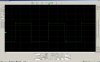
I should have mentioned this. When I say the output signal goes wild, I mean on my other scope, which is 2 channel, and each channel is connected to a home made box of tricks called a Scopematch. It shows antenna current and voltage phase before the impedance matching transformer and loading coil.

If it "goes mad", rather than just showing a stable impedance mismatch or frequency mismatch it usually means the amp is trying to send out a signal wildly off frequency, which it perhaps would try to do if the input to thr driver chip was corrupted?? Actually typing all this out makes me think a bit more slowly, to me this sounds quite a likely cause, if the mismatch is great enough the SWR will be through the roof and the current in the PA FET's similarly sky high? (Thinking aloud...).

Scopematch info here. https://njdtechnologies.net/want-a-...-meter-alone-can-provide-meet-the-scopematch/
 
Perhaps interestingly, no I cannot. With my cheap Chinese supposedly 200 MHz probe set X10 as in the other captures above, as soon as I probe on the driver chip side of either C1 or C2 the output goes wild, similar to how it goes if a FET is going to go bang, I will probe on the 74F74 sides of C1 and C2 and see what happens, fingers are crossed... Hmm that probes fine, and if I just touch the driver chip sides of C1 or C2 the signal goes wild. The capture should be attached, thanks very much spec!
Hi CW- no problem.

I am really intrigued by the odd behavior when you put the scope probe on the inputs to the NMOSFET drivers. The scope probe should be 10 M Ohms in parallel with around 10 pF which should not affect that node.

The output from the 74F74 looks as clean as a whistle, and that particular 74F74 is producing a high level of 3.4V and an amplitude 3.2V. The worst-case threshold of the IR2110 is 3.6V (higher than I said before) and the capacitor and resistor will reduce the positive excursion and that may be why you scope probe is just attenuating the signal sufficiently to cause ambiguity at the IR2110 input.

Just so that we are singing from the same hymn book, the IR2110 data sheet that I am using is @ https://www.infineon.com/dgdl/ir2110.pdf?fileId=5546d462533600a4015355c80333167e and specifically table 12B.

Can you do this:
(1) Disconnect the gate drive wire of each twisted pair wires from the IR2110 outputs.
(2) Connect the gate driver wires of each twisted pair wires to 0V (this will turn both NMOSFETs securely off and thus protect the NMOSFETs).
(3) then can you scope the inputs to the IR2110
(4) can you also scope the outputs of the IR2110

spec
 
Last edited:
This data sheet does seem to match this driver IC, yes.

I may have tried to be too clever, but to avoid some tricky de-soldering I removed the 50V supply to the drains and re did the
measurements with the following captures obtained. Note changes in voltage scaling. Thanks for your tireless interest!!
 

Attachments

  • pin10-driver-ic-no-PA-volts.jpg
    pin10-driver-ic-no-PA-volts.jpg
    494.2 KB · Views: 120
  • pin7-driver-ic-no-PA-volts.jpg
    pin7-driver-ic-no-PA-volts.jpg
    500.8 KB · Views: 153
OK thanks.

Can you now put a short across the capacitor at the output of the 74F74 and repeat the same measurements.

spec
 
OK, same probing as before, same scope settings, but with C1 shorted across so it's effectively no longer in circuit. Your patience is remarkable! Sincere thanks :)
 

Attachments

  • pin10-driver-ic-no-PA-volts-c1-shorted.jpg
    pin10-driver-ic-no-PA-volts-c1-shorted.jpg
    484.6 KB · Views: 153
  • pin7-driver-ic-no-PA-volts-c1-shorted.jpg
    pin7-driver-ic-no-PA-volts-c1-shorted.jpg
    483.1 KB · Views: 174
Gate when output just went "funny". No blown FET but output transformer heats up darned fast and Scopematch goes berserk. This is from tonight's transmissions.
 

Attachments

  • gate-when-output-goes-wild.jpg
    gate-when-output-goes-wild.jpg
    499.4 KB · Views: 178
Hi CW,
Gate when output just went "funny". No blown FET but output transformer heats up darned fast and Scopematch goes berserk. This is from tonight's transmissions.

Is this fault condition with the 74F74 output capacitors effective or with the capacitors shorted out.

spec
 
(1) Can you ensure that, if present, pin 4 is not connected to anything.

spec
 
I suspect that there is not sufficient high frequency decoupling of the IR2110 supply lines- gate drivers are particularly touchy about decoupling. The 74F74 may also have insufficient high frequency decoupling.

Can you connect a 100nF ceramic capacitor (no other capacitor type will do) with as short a leads as possible physically across the following pins of the IR2110:
(1) VDD [9] to VSS[13]
(2) VB[6] to VS [5]
(3) VCC[3] to COM [2]
Can you also connect a 100nF ceramic capacitor across the following pins of the 74F74;
(4) VCC [14] to GND [7]

spec
 
Hi again, looking at your posting times it seems stamina is another of your strong traits alongside patience. Enviable ;)

I have to do "things for her indoors" this morning, but I have a feeling you are onto something here as when I touch pins 10 or 12 on the driver IC it seems to break into some sort of oscillation. I also see small 50Hz spikes on the 50V supply. I have tamed this substantially by winding both 50V leads through an FT240-43 ferrite ring, but I think the material is sub optimal. I did think the schematic I built to seem sparse on de-coupling caps. I have the IC's socketed and have spares, so will solder direct to the pins of the IC's I do have 100nF (o.1uF) ceramics. I will add these. I have a 100nF poly film across the 12v supply pin to the little PCB that I bought off the designer in the USA. He seems to have disappeared, so I will either have to make my own or use perfboard that has a ground on one side to make any more. So a film cap is no good for de coupling? I didn't know that, I will brush up on this! Looking at which pins you say to de-couple, I realise the *5V* supply has no de-coupling at all, and presumably that's "more sensitive" to disturbance? I am learning slowly from all this, it's fascinating and useful, thank you very much indeed. I'll be back when I have done my jobs, not sure how long, probably mid afternoon. I'll post a photo of the build, that's looking a bit ropey now due to various mods and fiddling, I will rebuild once it's sorted.
 
Hi CW,


Is this fault condition with the 74F74 output capacitors effective or with the capacitors shorted out.

spec


With them in circuit. I cannot run without them as I have proven that one pin of the driver is always high with no signal and without these caps. I run the amp powered up all the time, only the input signal applied sets it into action. If I tried to run with these caps shorted and no signal I am sure a pair of FET's would just go bang. I did wonder if the drive signal would be "stronger" if the value of the caps were to be increased. I attach a circuit from a UK amp designer that shows how the capacitive driving of the FET's is normally done on these LF amps. Pluse he has some nice safety circuits.


As an aside, I also use similar(ish) software to WSPR for digital communications, something called OPERA. It too injects audio, but there's little documentation on just how it works. The reason I mention this is that when using OPERA the amp is FAR more likely to break into this "oscillation" or whatever it's doing, at the start of a TX, than using WSPR. The levels of the drive seem similar. Thanks spec.
 
With them in circuit. I cannot run without them as I have proven that one pin of the driver is always high with no signal and without these caps. I run the amp powered up all the time, only the input signal applied sets it into action. If I tried to run with these caps shorted and no signal I am sure a pair of FET's would just go bang. I did wonder if the drive signal would be "stronger" if the value of the caps were to be increased. I attach a circuit from a UK amp designer that shows how the capacitive driving of the FET's is normally done on these LF amps. Pluse he has some nice safety circuits.

Hi Chris,
I have been stating that the 7474 will have one output high on power up, without the DC blocking caps one pair of the MOSFETs will blow.

Eric
 
Hi again, looking at your posting times it seems stamina is another of your strong traits alongside patience. Enviable ;)

I have to do "things for her indoors" this morning, but I have a feeling you are onto something here as when I touch pins 10 or 12 on the driver IC it seems to break into some sort of oscillation. I also see small 50Hz spikes on the 50V supply. I have tamed this substantially by winding both 50V leads through an FT240-43 ferrite ring, but I think the material is sub optimal. I did think the schematic I built to seem sparse on de-coupling caps. I have the IC's socketed and have spares, so will solder direct to the pins of the IC's I do have 100nF (o.1uF) ceramics. I will add these. I have a 100nF poly film across the 12v supply pin to the little PCB that I bought off the designer in the USA. He seems to have disappeared, so I will either have to make my own or use perfboard that has a ground on one side to make any more. So a film cap is no good for de coupling? I didn't know that, I will brush up on this! Looking at which pins you say to de-couple, I realise the *5V* supply has no de-coupling at all, and presumably that's "more sensitive" to disturbance? I am learning slowly from all this, it's fascinating and useful, thank you very much indeed. I'll be back when I have done my jobs, not sure how long, probably mid afternoon. I'll post a photo of the build, that's looking a bit ropey now due to various mods and fiddling, I will rebuild once it's sorted.

Hi CW,

yes, I am a bit of an anorak when it comes to electronics. I often wake around 3am to 4am and read or post on ETO, before going back to sleep again.

Hmm- so you built this circuit yourself and also you seem to have a flexible approach. That is good because it possibly opens the way to circuit optimizations and changes in the layout which hopefully could sort the problems. Decoupling is a big topic especially in a circuit like this. What surprises me is how good the signal from the 74F74 is, but the F series of logic chips were always nice.

The fact that the chips are in sockets also helps modifications as a chip change may also be advisable.

How much current are the NMOSFETS switching?

Can you post a picture of the physical layout?

Just like you have to tend to 'her indoors', my son and his wife are visiting today for Sunday lunch. My son has been a big disappointment- he defected to software design.:D

So, I too, will be off air (until around 8pm).

spec
 
Hi Chris,
I have been stating that the 7474 will have one output high on power up, without the DC blocking caps one pair of the MOSFETs will blow.

Eric


Yes, another amp I built had a chip checking for the presence of an input signal and holding off a 4013 that drove the FET driver IC. It worked but added complexity and more wires to inductively couple to, which I suspect is a potential issue with this sort of thing. It's for this reason ost people capacitively couple the driver IC on these LF amps, as blow ups were common. Some sending CW had a permanent signal in and turned the HV to the power FET's on and off with another FET. Thanks Eric.
 
hi Chris,
Have you got a copy of this IR2110 app d/s.?
It may help in your diagnosis.
Eric
 

Attachments

  • an-978.pdf
    425.2 KB · Views: 113
I attach a circuit from a UK amp designer that shows how the capacitive driving of the FET's is normally done on these LF amps. Pluse he has some nice safety circuits.
Hi CW,

Can't see the circuit, which is a shame because it sounds interesting:cool:

spec.
 
Can you describe exactly what happens when the NMOSFETs have blown: just one NMOSFET, two NMOSFEts, all NMOSFETs?

spec
 
Sorry, the wife had other ideas for yesterday. Adding the caps did not fix the occasional scrambling of the output, when a TX started, but what they DID fix was a long running saga of the output from the FETs going berserk at shut down. I have a zip file showing the signal to the gates decay as a series of scope grabs as I scroll along after a single shot capture as TX ends. I now have to believe this was caused by the reverse current causing high RF and it getting into either the driver chip or the flip flop. Adding those by pass caps has fixed this, and hopefully the blown FET's too. Thank you VERY much!

The occasional oscillation or whatever at start up seems to have been fixed by a different approach. instead of driving the amp circuit with my Kenwood TS-580 transceiver's low power DRV socket output into a pre amp and then a doubler circuit, i completed a new gizmo called a QRP Labs U3S. Computer independent this produces a x2 signal with WSPR or OPERA or whatever protocol generated internally. So far a few tests with this device have shown zero start up shenanigans, but it's early days. To use the output from the Si5351a chip I had to remove the 51 Ohm resistor in parallel with the input on the amp board or signal level was too low to properly drive the 74F74 IC. Once I had done that things seem fine so far.... I am still curious (more than curious actually, as I need to learn why things occur...) why this oscillation started sometimes when using the TS-590, pre amp and doubler. maybe RF getting into something?

I attach the zip file showing how, pre the 0.1uF ceramic bypass caps being added, shut down of a TX session sent the output wild, and this link should take you to an alternative UK design for a similar LF / MF amp. This MF design can be used on LF with some cap and coil changes. I am building one at the moment.

UK amp design:

https://www.g0mrf.com/630m.htm

Gates waveform zip file too big for the forum, link to it is:

https://www.gatesgarth.com/waveforms.zip

As to which FET's would blow at the end of a TX sequence, it would be one or both on one side of the push pull, I do not recall one or both of both sides failing simultaneously.

The caps I added were soldered directly to the pins of the two IC's, so I guess I can do a sanity check and fit two un-doctored IC's later to see if the noise on the gates at the end of a TX session returns.

So far so good, fingers crossed and all that, will update later, but I believe great progress has been made by the caps and by using a different driving set up. Sincerest thanks to all.
 
Hi CW,

Thanks for additional information. Glad you are making some progress.

I have done an analysis of the whole circuit now and have found a number of issues- one issue relates to the problems you are having with keying on and off the NMOSFETs. The fact that the NMOSFETs are blowing individually and/or in pairs on the same side supports this

At the moment, I am working on solutions and an improved circuit, which was badly delayed because my misus deemed that we were going out for lunch today, followed by tea and cakes at her favorite tea room. Also, my brain is only firing on one cell after a rather late night at the pub yesterday.:)

spec

PS: What is the baud rate of the RS232 input?
 
I am not using the RS232 input at all spec. The amp is permanently powered up, and is "on line" only via a signal being sent into it. Alcohol is a great stress reliever, you have my abject support for contra tea room jollies ;) I await your analysis with great interest thank you.
 
Status
Not open for further replies.

Latest threads

New Articles From Microcontroller Tips

Back
Top