Continue to Site

Welcome to our site!

Electro Tech is an online community (with over 170,000 members) who enjoy talking about and building electronic circuits, projects and gadgets. To participate you need to register. Registration is free. Click here to register now.

  • Welcome to our site! Electro Tech is an online community (with over 170,000 members) who enjoy talking about and building electronic circuits, projects and gadgets. To participate you need to register. Registration is free. Click here to register now.

Water sensor help urgent required !

Status
Not open for further replies.

yusuf

Member
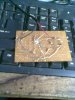
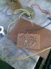
Hello friend here in my attachment this is a corrosion free water sensor but I want to add LED instead of outocoupler to indiacate.
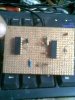
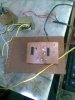
I have assembled all the components on breadboard but I am confused and not understanding whether it is running or not I have checked supply on electrodes and output where autocoupler is there by adding a diode but I didnt get any supply in both of them while putting the electrodes in water and by removing from water.
I am new in electronic so friend please suggest a good idea or how to check whether it is working or Not.
On more thing I am using on 6vlt and I dont have exact values capacitor so I have used 103 (it's the number printed on capacitor) yellow ones non polarize capacitors.

Thanks advance.
 

Attachments

  • sensor.gif
    sensor.gif
    13.9 KB · Views: 221
Firstly, the '103' (= 10nF ) capacitors will be ok, but the pulses fed to the probe will have a frequency about 5 times lower than if C1 were 1.8 nF. You don't say how you checked the supply, but I'm assuming you have a multimeter. If I understand you correctly you have replaced the optocoupler with an LED. That is ok.
I have run a simulation of your circuit, and when the probe resistance is less than ~ 500k ohms the LED lights.
Check you have all the diodes the right way round and that the CD4093 pins are correctly connected. You can test your circuit by temporarily shorting the probe contacts to each other. The LED should light. If it doesn't, measure the voltages at pins 2 and 3 of the CD4093 and let us know what they are. Be aware that this chip can be damaged by static electricity.
Water can have a surprisingly high resistance, depending on its purity, so it's possible (though unlikely) that the immersed probe reistance is > 500k, which would prevent the circuit working.
 
Hello alex thanks for your reply . I have checked all thing properly in first ic which is left in circuit diagram has 0v on pin 2 and 3 while second ic which is right in circuit diagram has 0v on pin 2 and approx. 2.50 v on 3 pin.. Friend please help..
 
Make sure the unused inputs... pins 8, 9, 12, and 13...are tied to ground.

ken

Added: It works for me on a breadboard with 0.01uF caps and the unused pins grounded. If the oscillator is working you should see ~3V"AC" on your DVM between the PROBE end of C2 and ground. If the oscillator is working OK and you short the probes together, you should see ~5V"DC" on your DVM between the pin 6 and ground and the LED should light. I used a 1K for R3 and a red LED in place of the opto-coupler.
 
Last edited:
Thanks kmoffett for your reply but please send me the circuit diagram as you have said because i am new in electronic and i please required circuit diagram.. Please send..
 
Hi yusuf,

you have everything in the circuit except for the probes.

Use a 47KΩ or 100KΩ resistor where the schematic is labeled "probe".

I suggest to use a 100nF capacitor (C4, instead of 3.3nF) to be charged by the probe return voltage.

Instead of an optocoupler connect a visible light LED the same way as the LED inside the optocoupler. Observe the max LED current to calculate for the current limiting resistor.

As the output is connected directly to the LED the LED won't get the necessary current anyway. (Max output sink current is generally 4 to 5mA making the LED glow dimly.)

To have the LED lit brightly use an NPN-transistor. Connect its base to pin 4 using a 6.8KΩ resistor. Connect the emitter to ground and connect the LED and current limiting resistor in series to the positive rail of your power supply.

The LED current limiting resistor is calculated: R(limit(Ω))=(+VB(V)-VBE(V)-Vf(V))/If(A) where +VB is the supply voltage, VBE is the base-emitter voltage drop, Vf is the LED forward voltage and If is the LED current.

Assuming a green LED with a forward voltage of 2.4V and a forward current of 20mA(0.02A) use those values for a 9V power supply the formula should read R(limit)=(9V-0.7V-2.4V)/0.02. R(limit)=295Ω. The next higher standard resistor value is 330Ω. The new LED current is calculated by dividing the voltage drop over the transistor and resistor by the value of the resistor: 5.9V/330=~17.9mA.

The resistor has to dissipate 105.61mW. So using a 250mW rated resistor is sufficient.

Boncuk
 
Last edited:
Are you measuring voltages with a digital voltmeter (DVM) ? It needs to be a high resistance meter (most, if not all, DVMs are) or you will get misleading measurements. With the probe input pins shorted together a DVM set to the 10V DC (or above) range and its negative probe connected to circuit ground should read about 3V at pin 3, 3.6V at pins 5 and 6 and around 1-3V at pin 4 of the circuit you posted. Please confirm the voltages there and your meter type.
As Boncuk points out, with the 4093 chip driving the LED directly the LED won't be very bright. All unused inputs of the chip should be connected to circuit ground.

in first ic which is left in circuit diagram has 0v on pin 2 and 3 while second ic which is right in circuit diagram has 0v on pin 2 and approx. 2.50 v on 3 pin
You're not using two ICs are you? (Only one IC is needed as it contains 4 gates).
 
Last edited:
Thanks alec butI have test all properly I am getting the volatge as I have told before in my post.
But It is not working so please help me in this problem... ! So you say that I have to connect all the unused pins to ground...
Will it destroy the IC while connecting all the unused pins to ground.
 
So you say that I have to connect all the unused pins to ground...
Will it destroy the IC while connecting all the unused pins to ground.

No, you connect all unused "input" pins (8, 9, 12, and 13) to ground. Do not connect the unused "output" pins (10 and 11) to ground...leave them open.

I'm assuming you are using one of the white prototyping breadboards to assemble you circuit. My suggestion would to take everything apart and start assembling it again from scratch. With a pen or highlighter, mark over the schematic lines as you make your circuit connections.

ken
 
Last edited:
While grounding the unused pins will the IC work..
Or not
 
....

As the output is connected directly to the LED the LED won't get the necessary current anyway. (Max output sink current is generally 4 to 5mA making the LED glow dimly.)

To have the LED lit brightly use an NPN-transistor. Connect its base to pin 4 using a 6.8KΩ resistor. Connect the emitter to ground and connect the LED and current limiting resistor in series to the positive rail of your power supply.....

Boncuk
Rather than add a resistor and transistor, just use the unused gates in parallel. Connect pins 5, 6 ,8 , 9,12, and13 together. Connect pins 4,10, and 11 together. This will easily handle 10mA for the LED.

Ken
 
Last edited:
But friend i am not getting any supply on ic .... And my circuit is not working ... Please help ?
 
We don't know. Ungrounded, unused gate inputs can cause problems, but we don't know what other problems your circuit may have. As I said in post #5, the circuit you presented in your first post (but with the unused gates grounded) worked for me. Take your circuit apart and reassemble it carefully. I've had to do that before, and in the end it worked but I never knew why. :( Can you post a "good" photo of you circuit?

Ken
 
Last edited:
I didn't suggest that you connect all unused pins to ground: I only mentioned unused input pins. Connecting output pins to ground could damage the IC.
Your measured voltages indicate that (1) the circuit you have built isn't the same (apart from the cap values) as in the schematic, or (2) your meter resistance is too low and is affecting circuit operation, or (3) the 4093 IC is faulty.
If the circuit is exactly as in the schematic but the gate input voltage at pins 5 and 6 is 0V and the gate output at pin 4 is 2.5V either the IC is faulty or your meter resistance is too low. If you don't have any supply voltage on your IC, as you state, then a wire isn't connected properly or the supply is shorted or the battery is dying under load.
 
Last edited:
Friend i do not have good camera but i have reassembled on new breadboard and i have not ground unused pins i had make same as which in circuit diagram but now also same response no voltage and it's not working...
I am using 103(the number printed on yellow capacitors which is non-polarize)..
and i am using 6v dc supply ?because i dont have 12volt dc...
 

Attachments

  • Image000.jpg
    Image000.jpg
    348.1 KB · Views: 150
  • Image001.jpg
    Image001.jpg
    320.1 KB · Views: 163
Last edited:
You are holding the board too close to the camera. Notice that the wires in the background are focused correctly. Take your pictures with the board that far away. Then use software like MS Paint to zoom in.

And it looks like you are using two ICs. Why?

Ken
 
Last edited:
And it looks like you are using two ICs. Why?
I asked that in post #8 but got no reply:)


i have not ground unused pins
Why not? Any gates with floating inputs are prone to oscillate or make the circuit behave erratically. You have been advised to ground unused inputs.

Do you have a connection from V+ to pin 14 (or if you are using two ICs, to each pin 14) and from pin 7 to ground (or if you are using two ICs, from each pin 7 to ground) ?
 
Last edited:
Ok friend here it is my photos ?
I am using 103(It is printed on yellow capacitors which are non-polarize) capacitor because i am not getting the exact values.
and I am using 6v dc power supply because i dont have 12v dc...
Please check what is the problem in this circuit why this circuit is not working ..

hi alec i am using 2 Ic because it is in the circuit diagram for corrosion free water sensor..
please acknowledge :

thanks in advanced..
 

Attachments

  • sensor0.jpg
    sensor0.jpg
    341.5 KB · Views: 147
  • sensor1.jpg
    sensor1.jpg
    349 KB · Views: 156
Last edited:
I can't tell from the pics; is your circuit assembled on perforated-only board or on perforated board having copper strips?
 
Status
Not open for further replies.

New Articles From Microcontroller Tips

Back
Top