Continue to Site

Welcome to our site!

Electro Tech is an online community (with over 170,000 members) who enjoy talking about and building electronic circuits, projects and gadgets. To participate you need to register. Registration is free. Click here to register now.

  • Welcome to our site! Electro Tech is an online community (with over 170,000 members) who enjoy talking about and building electronic circuits, projects and gadgets. To participate you need to register. Registration is free. Click here to register now.

Voltage Fluctuation In SMPS

Status
Not open for further replies.
Hi,
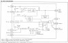
I have a UC3842 IC which is working good when powered from a wall adapter (18V)
it generates pulses at the output pin n everything looks fine frequency is 100KHz
but when i power it directly from AC220 via 18(V) Zener and 100K resistor divider voltage drops. i checked voltage in parallel to Zener before putting IC in socket and it reads 18V but after placing IC in socket (Actually a Bread Board) it starts fluctuating between 15 to 10 volts and then rises to 15V and drops to 10 and it continues but when powering from wall adapter it operates normally no voltage drop. Zener is 18V (1/4W) and resistor is (100K 1W) and after bridger rectifire there is a capacitor (450V 300uf) and before rectification there is another capacitor parallel to AC plug non polar (0.1uf 250V) (dont know why its used).....

Kindly Help....
Thanks In Advance.
 
Please post a schematic of your circuit (wall-wart AND mains supply examples).
 
HI,
here is the schematic.
UC.JPGUC3842 Flyback Converter.GIFUC3842 Flyback Converters.gif

first is the schematic for direct power from 220V mains 2nd is the actual circuit for uc3842 that i will follow but for testing and playing with current and voltage feedback parts i have excluded isolator and transformer part and just viewing the wave form on oscilloscope from the output pin but it gives gives waveform for less than a second and then power goes down to 10 volts and it continues....
 
HI,
here is the schematic.
View attachment 71368View attachment 71369View attachment 71370

first is the schematic for direct power from 220V mains 2nd is the actual circuit for uc3842 that i will follow but for testing and playing with current and voltage feedback parts i have excluded isolator and transformer part and just viewing the wave form on oscilloscope from the output pin but it gives gives waveform for less than a second and then power goes down to 10 volts and it continues....

It will - it can't work without the transformer, as the transformer powers the circuit.
 
hi,
it means only zener is not enough to power this circuit...?
and how that aux winding of transformer can power this circuit.....
it seems i have to completely connect transformer only aux cant power because there is no change of flux in aux without switching of primary winding?
 
What Nigel said another way:

The 150k resistor is not intended to run the IC but to start the IC.
The IC pulls very very little current when the supply voltage is low. The RC charges up to the start voltage. Now the IC starts and pulls POWER. The supply voltage drops. In your case until it stops working. In a real supply the transformer will supply power for the IC to use. (boot strap)
 
HI,
Now i have connected transformer and i checked voltage at current sense pin its not above 1volt its lest than 0.2 volt and i checked voltage at feedback pin and its less than 2.5 volts even i grounded both pins and then powered on the circuit and i am getting this output on gate pin and it looks like it starts and then reset and then starts and reset kindly guide in this regard...1.JPG2.JPG3.JPG4.JPG5.JPG6.JPG
 
n now that IC has blown because i connected current sense to ground via 1k resistor......i think i need more time to understand the working of UC3842 what i learnt from these experiments is that feedback voltage is fixed internally at 2.5 volts and current sense is fixed internally to 1 volt and via optocoupler part which is a feedback from secondary side of transformer we are giving (kind of pulses may be) to feedback pin when it gosed above 2.5 volts it switched of transistor and when it goes below 2.5volts it again switches on the transistor an hence it keeps monitoring the output and regulates it (am i right..?) and we cannot provide direct voltage at feedback pin of uc3842 via potentiometer...?
and current sense pin monitors voltage when it goes above 1 volt it swithes off transistor (if someone please explain the working...?)
 
feedback voltage is fixed internally at 2.5 volts and current sense is fixed internally to 1 volt

This may be a translation error. (I don't know your location) The voltages are not fixed. It is true that when the supply is running correctly the feedback voltage is 2.5V but it is not fixed.

Look at the block diagram.

The voltage on FB is compared to 2.5V.
....If FB is less than 2.5V COMP goes up in voltage.
....If FB is more than 2.5V COMP goes down in voltage.
....If FB is equals 2.5V COMP stays at the same voltage.
....The speed of COMP is set by a capacitor on the outside.

(COMP-1.4V)/3 this voltage goes to a voltage comparator that compares the voltage at CS.
....If CS is below (COMP-1.4V)/3 output=on
....If CS is above (COMP-1.4V)/3 output=off
........Output= off during part of the oscillator time period.

The voltage on CS comes from the current in the FET, Transformer. It should be a ramp. It should start at 0. There is a "spike" when the FET turns on. Then the current (voltage) should ramp up to a voltage (COMP-1.4V)/3 where the FET turns off and the current drops to zero. This ramp is because: (supply voltage, inductance in the transformer, time.) Without this ramp the IC can not work, or will be at maximum duty cycle!
 

Attachments

  • Untitled.jpg
    Untitled.jpg
    165.8 KB · Views: 669
hi,

thanks for explanationUC3842 Flyback Converter.GIF
can you please explain the optocoupler part....
and in this case vfb is fixed and only current is being sensed?
large flow of current means low duty cycle as vsense (from Rs) increases...?
Thanks in advance...
 
In most error amplifiers there are capacitors. I find no capacitors at pin 1-2 of the IC and also no capacitors at the TL431. This is strange.

The opto-coupler allows the power supply to see the voltage across isolation.

The error amplifier in the IC is looking at the FB pin and is trying to keep this voltage at 2.5V. The 150k resistor reduces the amplifier's gain.
The transistor side of the opto coupler is pulling up on FB while a 15k resistor is pulling down.
The TL431 is the error amplifier in this case.
....If the input of the TL431 is below 2.5V it will pull very little current through the LED.
....If the input of the TL431 is above 2.5V it will pull much current through the LED.
The LED current turns on the opto-transistor, which pulls up FB.

There should be a capacitor across the TL431 to slow down the amplifier.

Hi Ron

So many Brilliant people/members here. You are one of them.

Great post above. I learn't stuff too.

Thank's
tvtech
 
Last edited:
The TL431 can be used to do many different jobs. I have made an audio preamp with one.

Inside there is a op-amp with its positive input going to a 2.5V reference and its negative input going to the outside. The output of the op-amp only pulls down, not up, an external resistor pulls up. The output can not go below 2.5V.

The TL431 also makes a good voltage comparator.

See them often working with the Opto Coupler on the Secondary side for Regulation in 54CM and smaller sets here.

Very reliable little buggers. The Chinese mark them as a Transistor on their boards though...so reads strange on a YEW in circuit.

Solution = take it out and check. In all my time, maybe 3? replaced. Good product :)

Regards,
tvtech
 
Last edited:
See them often working with the Opto Coupler on the Secondary side for Regulation in 54CM and smaller sets here.

Very reliable little buggers. The Chinese mark them as a Transistor on their boards though...so reads strange on a YEW in circuit.

Solution = take it out and check. In all my time, maybe 3? replaced. Good product :)

I don't think I've ever had to replace one?, exceptionally reliable devices, but of course they aren't under any stress, nor in a position to get 'fried' very easily.
 
Status
Not open for further replies.

Latest threads

Back
Top