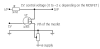
The other thing I don't like about this circuit. The gate voltage must charge up from 0 to 1.6V before anything happens. (long time) Then form 1.6 to 1.7V it goes through its entire range. (short time).
So I added a circuit that brings up the gate voltage to -6bd reduction (with not signal). Then the peak limiter just needs to charge from 1.6 to 1.65V. (better response)
So I added a circuit that brings up the gate voltage to -6bd reduction (with not signal). Then the peak limiter just needs to charge from 1.6 to 1.65V. (better response)
")