Continue to Site

Welcome to our site!

Electro Tech is an online community (with over 170,000 members) who enjoy talking about and building electronic circuits, projects and gadgets. To participate you need to register. Registration is free. Click here to register now.

  • Welcome to our site! Electro Tech is an online community (with over 170,000 members) who enjoy talking about and building electronic circuits, projects and gadgets. To participate you need to register. Registration is free. Click here to register now.

VCO explanation

Status
Not open for further replies.

Achelius

New Member
Hello from Greece !!!

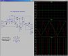
This is a Voltage-controlled oscillator (VCO). Αn oscillator that its frequency is controlled using a voltage signal. The VCO described here provide both triangular and square wave output. The control voltage can be varied between 5 mV to 5 V, to produce oscillation frequency from 10 Hz to 10 KHz.

Can someone please explain to me briefly the operation of the circuit ?

thank you

vco.JPG
 
LM101 is an Integrator fed by a current derived from the magnitude of the input control voltage. The output of the intergrator is the triangular wave output. The triangle amplitude trips a LM111 voltage comparator with a large hysteresis, so sets the peak amplitude (both positive peak and negative peak). The square wave output is used to switch the integrator such that it integrates either in the positive direction or the negative direction, depending the square wave.
 
Here is a sim of the simplified circuit for two different control voltages, 1V (green) and 2V (red). I'm using voltage-controlled switches in place of the JFets. They basically control the sign of the integration as a function of instantaneous polarity of the Sq wave.
 

Attachments

  • DF68.jpg
    DF68.jpg
    207.5 KB · Views: 303
thank you sir. Can you explain what is the filter C2 R7 ( his purpose ) and have a simulated waveform upon it. I would like to know his cutoff frequency.
 
thank you sir. Can you explain what is the filter C2 R7 ( his purpose ) and have a simulated waveform upon it. I would like to know his cutoff frequency.

The ancient LM101 was not internally compensated like modern opamps. The network provides the compensation externally. Not needed if you use a modern opamp.
 
Status
Not open for further replies.

Latest threads

New Articles From Microcontroller Tips

Back
Top