Continue to Site

Welcome to our site!

Electro Tech is an online community (with over 170,000 members) who enjoy talking about and building electronic circuits, projects and gadgets. To participate you need to register. Registration is free. Click here to register now.

  • Welcome to our site! Electro Tech is an online community (with over 170,000 members) who enjoy talking about and building electronic circuits, projects and gadgets. To participate you need to register. Registration is free. Click here to register now.

Using EdSim51 to show LCD

Status
Not open for further replies.

ZenZ94

New Member
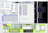
I am using EdSim51 to display LCD with Assembly language, but I could only display the 1st line LCD bar. Is there any existing command to call the 2nd line LCD bar?

here's my using code:
Code:
  ; put data in RAM
    MOV 30H, #'A'
    MOV 31H, #'B'
    MOV 32H, #'C'
    MOV 33H, #'D'
    MOV 34H, #'E'
    MOV 35H, #'F'
    MOV 36H, #'G'
    MOV 37H, #'H'
    MOV 38H, #'I'
    MOV 39H, #'J'
    MOV 3AH, #'K'
    MOV 3BH, #'L'
    MOV 3CH, #'M'
    MOV 3DH, #'N'
    MOV 3EH, #'O'
    MOV 3FH, #'P'
    MOV 40, #'Q'
    MOV 41H, #0    ; end of data marker


; initialise the display
; see instruction set for details


    CLR P1.3        ; clear RS - indicates that instructions are being sent to the module

; function set   
    CLR P1.7        ; |
    CLR P1.6        ; |
    SETB P1.5        ; |
    CLR P1.4        ; | high nibble set

    SETB P1.2        ; |
    CLR P1.2        ; | negative edge on E

    CALL delay        ; wait for BF to clear   
                    ; function set sent for first time - tells module to go into 4-bit mode
; Why is function set high nibble sent twice? See 4-bit operation on pages 39 and 42 of HD44780.pdf.

    SETB P1.2        ; |
    CLR P1.2        ; | negative edge on E
                    ; same function set high nibble sent a second time

    SETB P1.7        ; low nibble set (only P1.7 needed to be changed)

    SETB P1.2        ; |
    CLR P1.2        ; | negative edge on E
                ; function set low nibble sent
    CALL delay        ; wait for BF to clear


; entry mode set
; set to increment with no shift
    CLR P1.7        ; |
    CLR P1.6        ; |
    CLR P1.5        ; |
    CLR P1.4        ; | high nibble set

    SETB P1.2        ; |
    CLR P1.2        ; | negative edge on E

    SETB P1.6        ; |
    SETB P1.5        ; |low nibble set

    SETB P1.2        ; |
    CLR P1.2        ; | negative edge on E

    CALL delay        ; wait for BF to clear


; display on/off control
; the display is turned on, the cursor is turned on and blinking is turned on
    CLR P1.7        ; |
    CLR P1.6        ; |
    CLR P1.5        ; |
    CLR P1.4        ; | high nibble set

    SETB P1.2        ; |
    CLR P1.2        ; | negative edge on E

    SETB P1.7        ; |
    SETB P1.6        ; |
    SETB P1.5        ; |
    SETB P1.4        ; | low nibble set

    SETB P1.2        ; |
    CLR P1.2        ; | negative edge on E

    CALL delay        ; wait for BF to clear


; send data
    SETB P1.3        ; clear RS - indicates that data is being sent to module
    MOV R1, #30H    ; data to be sent to LCD is stored in 8051 RAM, starting at location 30H
loop:
    MOV A, @R1        ; move data pointed to by R1 to A
    JZ finish        ; if A is 0, then end of data has been reached - jump out of loop
    CALL sendCharacter    ; send data in A to LCD module
    INC R1            ; point to next piece of data
    JMP loop        ; repeat

finish:
    JMP $


sendCharacter:
    MOV C, ACC.7        ; |
    MOV P1.7, C            ; |
    MOV C, ACC.6        ; |
    MOV P1.6, C            ; |
    MOV C, ACC.5        ; |
    MOV P1.5, C            ; |
    MOV C, ACC.4        ; |
    MOV P1.4, C            ; | high nibble set

    SETB P1.2            ; |
    CLR P1.2            ; | negative edge on E

    MOV C, ACC.3        ; |
    MOV P1.7, C            ; |
    MOV C, ACC.2        ; |
    MOV P1.6, C            ; |
    MOV C, ACC.1        ; |
    MOV P1.5, C            ; |
    MOV C, ACC.0        ; |
    MOV P1.4, C            ; | low nibble set

    SETB P1.2            ; |
    CLR P1.2            ; | negative edge on E

    CALL delay            ; wait for BF to clear

delay:
    MOV R0, #50
    DJNZ R0, $
    RET
 
You need to tell the display to go to the start address of the second line.
This is an example from some code I wrote several years ago.


MOVLW 0x80 ; Cursor at 0x00
call Send_Cmd

MOVLW 0x010 ; Write 16 characters from display buffer to top line of display
MOVWF TempByte2 ;
MOVLW rDisp ;
MOVWF FSR ;
CALL Send_next_Char ;


MOVLW 0xC0 ; Cursor at 0x40 (Start of second line)
call Send_Cmd

MOVLW 0x010 ; Write 16 characters from display buffer to bottom line of display
MOVWF TempByte2 ;
MOVLW rDisp+0x010 ;
MOVWF FSR ;
CALL Send_next_Char ;

; ------------------------------------------------

Send_Cmd MOVWF Cmd ;Put command byte in Temporary variable
CALL Check_BF ;Check if LCD is ready
MOVF LCD_PORT, W ;Get lower nibble of PORTB
ANDLW 0x0F ;
MOVWF Ctrl ;
MOVF Cmd, W ;
ANDLW 0xF0 ;Get upper nibble
IORWF Ctrl,W ;Combine command with Ctrl
MOVWF LCD_PORT ;
BCF RW ;Clear is for a write to LCD
BCF RS ;Clear is for command mode
CALL Toggle_E ;
MOVLW 0x0F ;
ANDWF LCD_PORT,F ;
SWAPF Cmd,W ;Swap nibbles
ANDLW 0xF0 ;
IORWF LCD_PORT,F ;
CALL Toggle_E ;
RETURN

; ---------------------------------------------
You will need to look at the data sheet on the display that you are using as the start address of the lines vary between displays with different line lengths.
I think bit 7 of the command means to move the address in the lower bits to the display position pointer. Again you will find the command format in the data sheet.

Les.
Thanks for reply. I would like to try your code but I have no idea why my compiler not allowed. Look like there're no such command like MOVLW in this compiler.
LCD.jpg


& the address u mentioned is that the picture below I found?
LCD addres.jpg


Sry for asking stupid question, I am a newbie who just started learning all this stuff for few weeks. Again, thanks for your kindness replying.
LCD_zps2k0wz3fh.jpg
 
Last edited by a moderator:
The program given by Les is for the PIC mcu. You cannot just simply copy and past it into your simulator. You have to understand the idea behind it and convert the idea to 8051 code in order to work.

Allen
 
thanks for replying guys, i did continued searching so i found out the example of the display of 2 line, but my code still didn't go right, could anyone take a look at it?

Code:
; put data in RAM
    MOV 30H, #'A'
    MOV 31H, #'B'
    MOV 32H, #'C'
    MOV 33H, #'D'
    MOV 34H, #'E'
    MOV 35H, #'F'
    MOV 36H, #'G'
    MOV 37H, #'H'
    MOV 38H, #'I'
    MOV 39H, #0


; initialise the display


    CLR P1.3     
; function set 
    CLR P1.7 
    CLR P1.6 
    SETB P1.5 
    CLR P1.4 

    SETB P1.2 
    CLR P1.2 

    CALL delay        ; wait for BF to clear 
             
    SETB P1.2     
    CLR P1.2 
             

    SETB P1.7 

    SETB P1.2 
    CLR P1.2     
         
    CALL delay 


; entry mode set
; set to increment with no shift
    CLR P1.7 
    CLR P1.6 
    CLR P1.5 
    CLR P1.4 
    SETB P1.2 
    CLR P1.2 

    SETB P1.6 
    SETB P1.5 

    SETB P1.2 
    CLR P1.2 
    CALL delay 


; display on/off control
; the display is turned on, the cursor is turned on and blinking is turned on
    CLR P1.7     
    CLR P1.6 
    CLR P1.5 
    CLR P1.4 
    SETB P1.2 
    CLR P1.2 

    SETB P1.7 
    SETB P1.6 
    SETB P1.5 
    SETB P1.4 
    SETB P1.2 
    CLR P1.2 

    CALL delay 
; set CGRAM address
CLR P1.7     
    SETB P1.6     
    CLR P1.5     
    CLR P1.4 

    SETB P1.2     
    CLR P1.2 

    CLR P1.6 
    SETB P1.2 
    CLR P1.2 

    CALL delay 
; set DDRAM address to 0H
CLR P1.3    e

    SETB P1.7     
    CLR P1.6     
    CLR P1.5
    CLR P1.4     

    SETB P1.2     
    CLR P1.2 

    CLR P1.7 

    SETB P1.2     
    CLR P1.2     

    CALL delay     
    RET

; send data
    SETB P1.3        ; clear RS - indicates that data is being sent to module
    MOV R1, #30H    ; data to be sent to LCD is stored in 8051 RAM, starting at location 30H
loop:
    MOV A, @R1        ; move data pointed to by R1 to A
    JZ finish        ; if A is 0, then end of data has been reached - jump out of loop
    CALL sendCharacter    ; send data in A to LCD module
    INC R1            ; point to next piece of data
    JMP loop        ; repeat

finish:
    JMP $


sendCharacter:
    MOV C, ACC.7     
    MOV P1.7, C         
    MOV C, ACC.6     
    MOV P1.6, C         
    MOV C, ACC.5     
    MOV P1.5, C     
    MOV C, ACC.4     
    MOV P1.4, C         

    SETB P1.2     
    CLR P1.2         

    MOV C, ACC.3 
    MOV P1.7, C     
    MOV C, ACC.2 
    MOV P1.6, C     
    MOV C, ACC.1 
    MOV P1.5, C     
    MOV C, ACC.0 
    MOV P1.4, C         
    SETB P1.2     
    CLR P1.2     
    CALL delay     

delay:
    MOV R0, #50
    DJNZ R0, $
    RET
 
Last edited:
Try to put the delay between SETB P1.2 and CLR P1.2 and see if it helps.

Code:
    SETB P1.2 
    CALL delay 
    CLR P1.2

And I think the delay is too short if you're running at 12 MHz.
Try this:

Code:
delay:
    MOV R0, #50
    MOV R2, #0
D1:
    DJNZ R2, $
    DJNZ R0, D1
    RET

Allen
 
Last edited:
I tried on the MCU 8051 IDE, with some changes to the hardware and software, and it does work; but intermittently.

There are also some funny characters on the right side of the second line and I couldn't figure out why it was there....

see attached

mcu 8051 IDE.PNG

Allen
 
Last edited:
ZenZ94,
It would be a great help if you comment you code well is the same way as the code above posted by absf. One thing you may not be doing is setting the display to 2 line mode. This is the code I used to initialize the display. (This is for a PIC16F628a)

; Initialize LCD
MOVLW D'200' ;
CALL X_Delay100 ; X_Delay100 delays by 100 uS x the value in the W register so this delay will be 2 mS
MOVLW 0x30 ;(LCD bits 4 & 5) - Set 4 bit mode command
IORWF LCD_PORT,F ;
CALL Toggle_E ;Send command
MOVLW D'50' ;
CALL X_Delay100 ;
CALL Toggle_E ;Send command again ?
MOVLW D'1' ;
CALL X_Delay100 ; This delay will be 100 uS
CALL Toggle_E ;
MOVF LCD_PORT, W ;Get lower nibble of PORTB ????? (R/W has not been changed for a read)
ANDLW 0x0f ; Clear high nibble (LCD data)
MOVWF Ctrl ;
MOVLW 0x20 ;
IORWf Ctrl,W ; "or" in bit 5
MOVWF LCD_PORT ; (LCD_PORT is just an equate to PORTB which is connected to the LCD)
CALL Toggle_E ;
; MOVLW 0x20 ;Set datalength to 4, 1 line, 5x7 font (Original setting)

MOVLW 0x28 ;Set datalength to 4, 2 line, 5x8 font (New setting)
CALL Send_Cmd ;
MOVLW 0x0c ;Display on, Curser off
CALL Send_Cmd ;

MOVLW 0x06 ;Screen shifting mode on

; MOVLW 0x04 ;Screen shifting mode off

CALL Send_Cmd ;
MOVLW 0x03 ;Return home command
CALL Send_Cmd ;

Les.
 
I tried to make the delay longer but it still go to the same way
the LCD display go with Function set no called error
error function.jpg

& This is the code I set the DDRAM address to oH
Code:
    CLR P1.3        
    SETB P1.7       
    CLR P1.6        
    CLR P1.5        
    CLR P1.4      

    SETB P1.2       
    CLR P1.2        

    CLR P1.7       

    SETB P1.2    
    CLR P1.2       

    CALL delay        
    RET


& This should be the code that set the DDRAM to 40H that the start of the line 2 display
Code:
CLR P1.3
SETB P1.7 
SETB P1.6 
CLR P1.5
CLR P1.4 

SETB P1.2
CLR P1.2 

CLR P1.7 
CLR P1.6

SETB P1.2 
CLR P1.2 

CALL delay 
RET
 

Attachments

  • error function.png
    error function.png
    765.1 KB · Views: 462
Allen.... Post the updated code..... I want to know why R1 has reached 0x3f
OK, here's the code:

Code:
    ORG    0
    JMP    START

    ORG     0030H

RS    EQU    P2.0
RW    EQU    P2.1
EN    EQU    P2.2
TEMP    EQU    40H
P1_TEMP    EQU    20H

START:
; put data in RAM
    MOV 30H, #'A'
    MOV 31H, #'B'
    MOV 32H, #'C'
    MOV 33H, #'D'
    MOV 34H, #'E'
    MOV 35H, #'F'
    MOV 36H, #'G'
    MOV 37H, #'H'
    MOV 38H, #'I'
    MOV 39H, #'J'
    MOV 3AH, #'K'
    MOV 3BH, #'L'
    MOV 3CH, #'M'
    MOV 3DH, #'N'
    MOV 3EH, #'O'
    MOV 3FH, #0    ; end of data marker


; initialise the display
; see instruction set for details

MAIN:
    CLR RW        ; R/W = 0
        CLR RS      ; clear RS - indicates CMD MODE
        CLR EN        ; ENABLE = 0

    MOV    TEMP,#28H    ;4 BIT MODE
    CALL    NLCD_CMD

    MOV     TEMP,#61H    ;
    CALL    NLCD_CMD

    MOV    TEMP,#0CH    ;SET CURSOR INCREMENT
    CALL    NLCD_CMD    ;& BLINKING

    MOV    TEMP,#80H    ;SEND CURSOR TO FIRST LINE
    CALL    NLCD_CMD    ;

; send data
    SETB RS         ; SET RS TO 1 - indicates that data is being sent
    CLR  RW        ; WRITE MODE
    CLR  EN        ;ENABLE
    MOV R1, #30H    ; data to be sent to LCD is stored in 8051 RAM,
                ; starting at location 30H
loop:
    MOV A, @R1        ; move data pointed to by R1 to A
    JZ finish        ; if A is 0, then end of data has been reached - jump out of loop
    CALL sendCharacter    ; send data in A to LCD module
    INC R1            ; point to next piece of data
    JMP loop        ; repeat

finish:
    JMP $

sendCharacter:

    MOV C, ACC.7        ; ORIGINAL CODE ADDING P1_TEMP
    MOV P1_TEMP.7, C    ; |
    MOV C, ACC.6        ; |
    MOV P1_TEMP.6, C    ; |
    MOV C, ACC.5        ; |
    MOV P1_TEMP.5, C    ; |
    MOV C, ACC.4        ; |
    MOV P1_TEMP.4, C    ; | high nibble set
    MOV P1,P1_TEMP    ; WRITE UPPER NIBBLE TO P1

    SETB EN             ; |
    CALL delay         ; wait for BF to clear
    CLR  EN             ; | negative edge on E
    CALL delay         ; wait for BF to clear

    MOV C, ACC.3        ; |
    MOV P1_TEMP.7, C    ; |
    MOV C, ACC.2        ; |
    MOV P1_TEMP.6, C    ; |
    MOV C, ACC.1        ; |
    MOV P1_TEMP.5, C    ; |
    MOV C, ACC.0        ; |
    MOV P1_TEMP.4, C    ; | low nibble set
    MOV P1,P1_TEMP    ; WRITE LOWER NIBBLE TO P1

    SETB EN           ; |
    CALL delay     ; wait for BF to clear
    CLR  EN            ; | negative edge on E
    CALL delay     ; wait for BF to clear
    RET

NLCD_CMD:
    MOV A,TEMP    ;GET CMD BYTE
    ANL A,#0F0H    ;GET UPPER 4 BITS
    MOV P1,A           ;WRITE TO P1
    SETB EN             ;SEND STROBE PULSE
        CALL delay      ; LET IT WAIT TO SETTLE
        CLR  EN           ; negative edge on E
        CALL delay      ; wait for BF to clear
        MOV A,TEMP    ;GET CMD BYTE AGAIN
        RL A                  ;shift left Acc 4 times
        RL A
        RL A
        RL A        ;LOWER NIBBLE becomes UPPER NIBBLE
        ANL A,#0F0H    ;DO SAME THING AS ABOVE
    MOV P1,A          ;WRITE TO P1
        SETB EN        ; | GIVE STROBE PULSE
        CALL delay     ; wait for BF to clear
        CLR  EN        ; | negative edge on E
    CALL delay     ; wait for BF to clear
    RET
delay:
    MOV R2, #50        ;DELAY 12MS
D1: MOV R3, #0
     DJNZ R3,$
     DJNZ R2,D1
    RET

        END

8051 lcd.PNG


[EDIT] I have to disable the delay when simulating, or else the sim would take forever to run.
 
Last edited:
I tried to translate portion of Les Jones's code to 8051....

Code:
; Initialize LCD
1    MOVLW D'200' ;
2    CALL X_Delay100 ; X_Delay100 delays by 100 uS x the value in the W register so this delay will     be 2 mS
3    MOVLW 0x30 ;(LCD bits 4 & 5) - Set 4 bit mode command
4    IORWF LCD_PORT,F ;
5    CALL Toggle_E ;Send command
6    MOVLW D'50' ;
7    CALL X_Delay100 ;
8    CALL Toggle_E ;Send command again ?
9    MOVLW D'1' ;
10    CALL X_Delay100 ; This delay will be 100 uS
11    CALL Toggle_E ;
12    MOVF LCD_PORT, W ;Get lower nibble of PORTB ????? (R/W has not been changed for a read)
13    ANDLW 0x0f ; Clear high nibble (LCD data)
14    MOVWF Ctrl ;
15    MOVLW 0x20 ;
16    IORWf Ctrl,W ; "or" in bit 5
17    MOVWF LCD_PORT ; (LCD_PORT is just an equate to PORTB which is connected to the LCD)
18    CALL Toggle_E ;

TRY TRANSLATING ABOVE CODE TO 8051

RS    EQU    P2.0
RW    EQU    P2.1
EN    EQU    P2.2
TEMP    EQU    40H
milli    EQU    41H
VAR1    EQU    42H
P1_TEMP EQU    20H

1    MOV    MILLI,#20    ;MOVLW D'200'
2    CALL    Delay_1mS    ;CALL X_DELAY100  (DELAY 20 MILLI-SECONDS)
3    MOV    A,#30H        ;MOVLW 0X30  (BIT 4 & 5= 1 *4 BIT MODE)
4    ORL    P1,A        ;IORWF LCD_PORT
5    CALL    TOGGLE_E    ;TOGGLE EN L->H
6    MOV    MILLI,#5 
7    CALL    Delay_1mS    ;DELAY 5 MS
8    CALL    TOGGLE_E    ;TOOGLE EN H->L
9    MOV    MILLI,#1
10    CALL    DELAY_1MS    ;DELAY 1MS (SHOULD BE 100US)
11    CALL    TOGGLE_E    ;TOGGLE ENABLE AGAIN L->H
12    MOV    A,P1        ;GET CMD DATA BACK
13    ANL    A,0FH        ;MASK OFF LOWER NIBBLE
14    PUSH    A        ;SAVE IT
15    MOV    A,#20H        ;NEXT CMD BYTE?
16    POP    B        ;RESTORE ACC IN B-REG
16    ORL    A,B        ;OR WITH #20, RESULT IN A
17    MOV    P1,A        ;WRITE TO lcd PORT
18    CALL    TOGGLE_E    ;toggle again
;-------CONTINUE WITH OLD CODE


Delay_1mS:
    mov VAR1,#230
d:
    nop
    nop
    djnz VAR1,d
    djnz milli,Delay_1ms
    ret

TOGGLE_E:
    CPL  EN         ;EN = NOT EN
     RET

How am I doing ?

Allen
 
Last edited:
I inserted the above Les's codes before my LCD_initialize routine and then enabled all the delays. Then it worked in Proteus but not in 8051 IDE with all delays disabled.

8051 LCD v2.PNG
 
Hi absf,
The subroutine Toggle_E does not just do a complement of the "E" pin of the LCF It does a set then a reset to send a short pulse.
Toggle_E
BSF E
NOP
BCF E
RETURN
I have now put the full source code in my Dropbox public folder.
It can be accesed via this URL **broken link removed**
I have given up trying to follow ZenZ94's code as it has so few comments and no table of equates to say which port bits connect to which signals on the LCD
The circuit you have just posted ties up which port bits controls which LCD pin.

Les.
Thanks...;)

I will correct my code here and test it first before I post it again.

Allen
 
Status
Not open for further replies.

New Articles From Microcontroller Tips

Back
Top