Electro Tech is an online community (with over 170,000 members) who enjoy talking about and building electronic circuits, projects and gadgets. To participate you need to register. Registration is free. Click here to register now.
Welcome to our site! Electro Tech is an online community (with over 170,000 members) who enjoy talking about and building electronic circuits, projects and gadgets. To participate you need to register. Registration is free. Click here to register now.
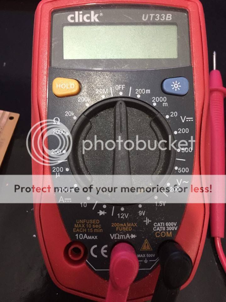
Put a 100R or near resistor in series with the meter leads and switch the meter to 100mA DC and measure the current at pin 7 of the 555. The other meter lead connects to the 0V line
i only have a 200r resistor, trying that i came with the following
i wasnt sure if i needed to do it powered up or not so i did both
unplugged 0
plugged in 31.7
OK. There is a short between pin 7 of the 555 and the 6V supply line.
Remove pin 7 of the 555 from the circuit and do the same measurement, either at the bottom of the 2K7 pull-up resistor, or pin 14 of the 4017. The meter should read between zero and around 3
definitely measured on pin 3 ill try and draw up a quick circuit of the other board and maybe you could see if its close and what changes i need to make? if you dont mind. it will only be in paint tho.
maybe i did something with a chip on this board
edit: actually i will redo the board and get back to you thanks
Can you fit a new one, but leave pin 7 disconnected.
Connect the negative lead of the meter to the 0V supply line. Switch the meter to 20V and check that pin 3 of the 555 is swinging between 0V and 6V.
Don't rush. Take your time. Have a beer or a coffee.
Let me know how it goes
spec
(PS: weather you have made a mistake or not is not relevant- I make mistakes all the time, and I have a mountain of blown components, especially loudspeakers to prove it. The only way to avoid mistakes is to avoid doing anything )
haha thanks ok i will switch out the 555, leave pin 7 disconnected and test, but first its definetly time for a coffee. should have it done in about 30 mins
This site uses cookies to help personalise content, tailor your experience and to keep you logged in if you register.
By continuing to use this site, you are consenting to our use of cookies.

")