Electro Tech is an online community (with over 170,000 members) who enjoy talking about and building electronic circuits, projects and gadgets. To participate you need to register. Registration is free. Click here to register now.
Welcome to our site! Electro Tech is an online community (with over 170,000 members) who enjoy talking about and building electronic circuits, projects and gadgets. To participate you need to register. Registration is free. Click here to register now.
WOW!!!! you guys are bloody awesome, im from australia so i only just woke up (8.45am) and this is incredible, im going to go down to the electronics store now and grab some extra bits and get stuck into it, I will keep you all updated, Thanks heaps
WOW!!!! you guys are bloody awesome, im from australia so i only just woke up (8.45am) and this is incredible, im going to go down to the electronics store now and grab some extra bits and get stuck into it, I will keep you all updated, Thanks heaps
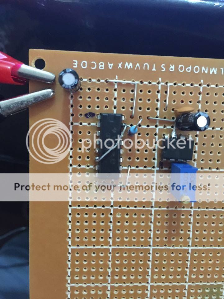
hey spec i have constructed issue 3, i am not getting anything, however when i test terminals to find a pulse i am receiving a pulse on pin 3 on the 555 chip
What is the transistor for "LBIP#7" for? The name has 6 letters and the 7th output resets the counter to light the first letter LEDs again. The 7th output will occur for such a short duration that if it drives an LED then that LED would not be visible. Instead of resetting the counter it would be nice if the 1st to 6th CD4017 outputs have series diodes feeding the 560 ohm resistors then the 7th to 9th outputs can drive a transistor to turn on all six transistors that drive the letters. The 10th output would be a pause without any LEDs lighted before the counter begins again.
Afraid I was knee deep in things when your post came in and I didn't have time to appriciate the wisdom of it.
Just a word about approach on this thread: Keshin is in a hurry as he stated in his opening post. He is also getting back into electronics, so the message is keep it simple. Not only that but he has the components already and does not have time to buy different components or search the internet for circiuits or use the this or that chip which might be the obvious way to go- he already has the components and the LED controller is already built, to another design.
Given a free hand I'm sure that we could all design a much better circuit. I could think of ways to radically improve this one, but it would not be appropriate. For example the BJT LED bank drivers woud be replaced by logic level MOSFETs. That would open up the way for all sorts of diode logic and so on. It would also stop overstressing the outputs of the counter. The other thing is that I do not know if Keshin has a buffered or unbuffered version of the counter chip. If it is unbuffered it will have a real struggle driving the 560Rs into the bases of the LED bank driver transistors. UPDATE MSI 4000 CMOS logic always have buffered outputs. It is only the SSI gates that are available with unbuffered outputs.
About circuit enhancements etc. The obvious way is to use a micro controller with s MOSFET driver array driving the LED banks. Then you could do anything with a few lines of code, but that would not get Keshin an introduction to building electronic circuits.
The goofs that you point out are much appriciated though. Don't forget either I am not only designing but schetching the circuit by hand then putting it into Eagle, which I am not familiar with. Then I have to export it as a png file then crop and enhance in Photoshop, then fight with the image posting antics of the ETO user interface, so I just do not have time for analysis, speculation and optimisation . As long as the basic architecture is sorted the circuit will work and that is all that counts. Having said that that the circuit is a lot better than some of the horrors that you se in magazines and on the net.
Quite honestly, having to answer all the speculative points that are being being made on this post is just delaying progress and making life difficult for me. Don't forget, I'm not being paid for all this work. Also, I am posting on other sites too plus a family and I also have to eat once in a while.
The other thing is that there are some very good circuits on ETO, but there are also many horrors. I could spend all my time commenting on those, but it would be a wastes of time.
But as I have already said, comments that point out fundermental flaws in the architecture or areas that could be improved are much appriciated and are welcome.
hey spec i have constructed issue 3, i am not getting anything, however when i test terminals to find a pulse i am receiving a pulse on pin 3 on the 555 chip
hey spec ok i just did a check and pin 7 appears to be live tested with led and 200 ohm resistor attached (no pulse) however if i do the same and test on pin 3 i get a nice pulse (on off on off)
edit: i forgot to mention thers is a low voltage coming out of each of the output pins on the 4017 but they are not pulsing just constant, i will grab my volt meter and get voltages if that helps
Pin 3 of the 555 will not drive a LED with 200 ohms in series with it. It is only designed to drive the high impedance of the counter input. Do you have a voltmeter? Best not to put the LED and resistor in various parts of the circuit or you will blow things up.
ooops haha ok well i have spares of each component now anyway, and i have my volt meter ready. i have skype if that would be easier to work through this, or on here is fine thanks for your patience
555
pin 1 0.01v
pin 2 bouncing 3.27 and 3.32
pin 3 bouncing between 3.20 and 3.30
pin 4 full 6.41
pin 5 0.01
pin 6 same as pin 2 on + cap side (chip side), on cap - side 0.01
pin 7 full battery voltage 6.41
pin 8 full 6.41
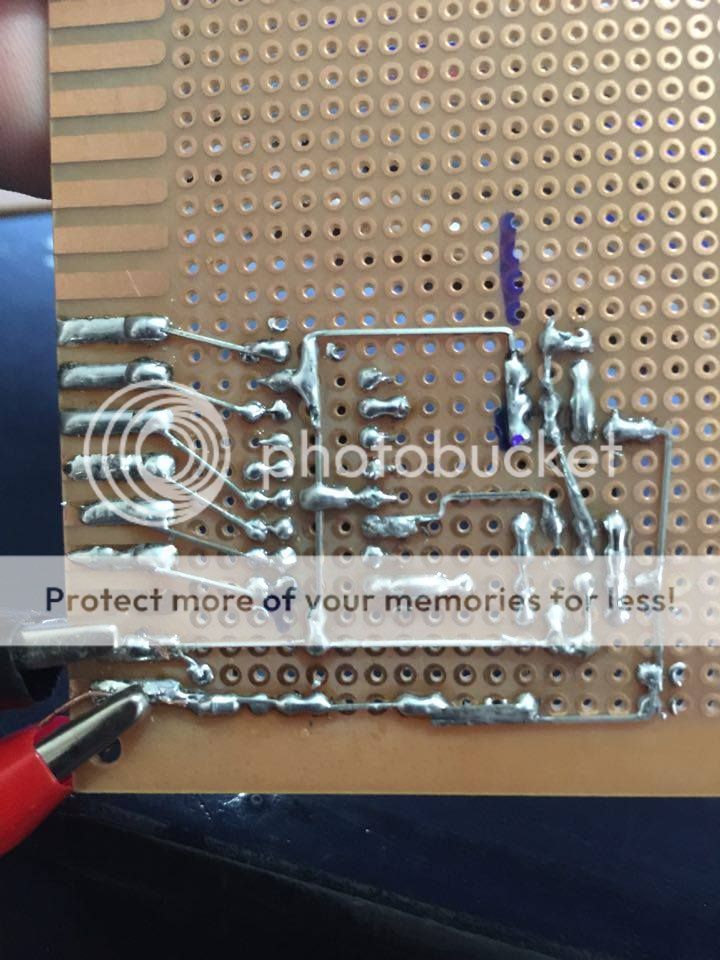
yes that is correct pin 7 is stuck up at it, no the chips arent in sockets i completely forgot i could do that, ill unsolder it and have another go maybe i have something touching something wrong
You dont have to rush, take your time. Get yourself a flux capacitor and learn to travel back in time, say 1 week ago, so you can have plenty of time to finish this project
Ok, now seriously, there is a trick you can use to buy more time, and it will benefit you as well as the beneficiary.
Build up a simpler circuit, for example, one that lights ALL the LED's at the SAME time, keeps them lit, or maybe turns them all off and then back on again...very simple....fast to build up.
Then, also include a nicely drawn card that reads:
"Coupon for 1 free upgrade after Christmas"
after which you promise to make the design much more interesting.
That will buy you time so you can do a really nice job and you both will be much happier.
hahahaha absolutley love that. hes only 2 years old but loves lights and flashing so thats what brought this on, however i have got the transistor/ led part working im just trying to figure out the chip part, i do have spares tho so this will be ongoing as im quite enjoying all of this. it has been about 10 years since iv played with this kind of stuff and im only 27 haha
No mistake. The discharge transistor in the 555 is blown.
But that is not a problem. When we can confirm that there is only a 2K7 resistor going to 6V and that the counter input is not blown you can just link pin 7 and pin 3 on the 555.
But we need to ensure there is no short to the 6V supply rail
This site uses cookies to help personalise content, tailor your experience and to keep you logged in if you register.
By continuing to use this site, you are consenting to our use of cookies.


") thanks for your patience
thanks for your patience