Electro Tech is an online community (with over 170,000 members) who enjoy talking about and building electronic circuits, projects and gadgets. To participate you need to register. Registration is free. Click here to register now.
Welcome to our site! Electro Tech is an online community (with over 170,000 members) who enjoy talking about and building electronic circuits, projects and gadgets. To participate you need to register. Registration is free. Click here to register now.
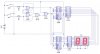
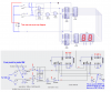
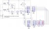
I am really sorry about this but the components to which i have made arrows towards i am not familiar with since they are not the same in my program of Circuit Wizard.
I am really sorry about this but the components to which i have made arrows towards i am not familiar with since they are not the same in my program of Circuit Wizard.
I just got a couple of questions, mostly about the theory im guessing, along with some general problems.
First, the number on the 7 segment always starts at either 99 or 11, but never 00. Granted, i can press the reset, but is there a way to make it default on 00?
Second, instead of two SPDT switches, is there a way to make it just one push to make on both end on the left??
Third, if one switch is on the 'top', not connected, only then does the other one work. If it is at the bottom, it doesn't. Why??
I just got a couple of questions, mostly about the theory im guessing, along with some general problems.
First, the number on the 7 segment always starts at either 99 or 11, but never 00. Granted, i can press the reset, but is there a way to make it default on 00? Add the cap across the RESET switch
Second, instead of two SPDT switches, is there a way to make it just one push to make on both end on the left?? The drawing shows two single pole normally OPEN push buttons.
Third, if one switch is on the 'top', not connected, only then does the other one work. If it is at the bottom, it doesn't. Why?? You have got it wired incorrectly!
hi,
If you are showing a '1' or '9' after the power up RESET, this indicates that the 4011 latching is either setting high or low after the RESET period.
You could try to lengthen the RESET period by increasing the value of the reset10K to say 22K and/or also the cap to 47nF.
Are you just simulating this circuit or actually building it.?
If you building the circuit its important that you add decoupling across the +9V and 0V lines, say at least 22uF cap and a 47nF or 100nF cap in parallel.
If its just a simulation the its not possible to say what the state of the 4011 will be at power up.?
hi,
Do you mean 'OR' the clocks from a PTM and a opto-detector output.??
That is possible, which type of opto do you have.?
If you are able to program a PIC, you would not need the 4029's or the 4011.!!
The count would be done in the PIC and the PIC would drive the transistor/LED's.
I am building this project that is an electronic piggy bank.
It would detect a coin when an opto-isolator IR connection is broken.
I want it to input the output of this into a PIC which can generate pulses to count up a certain number.
For example, if a 5p coin is inserted, 5 pulses should make the 7 segment count up 5 times.
However, i also want 4 push to make switches:
Two for counting up (one for up in pence, the other in pounds)
Two for counting down (one for down in pence, the other in pounds)
This is why i have been asking you these questions.
What do you think??
Thanks
=]
EDIT:
I had tried a PIC but found it difficult to count up and down. I use a GENIE PIC, the default microcontroller on circuit wizard.
hi,
I guess as you are working in pence/pounds your are in the UK.??
What you describe requires a PIC type processor.
If you try to build it with logic IC's its going to be a big problem.
I can help you with PIC cash counting program if you wish.??
If you had slots for say 5p,10 ,20p,50p, £1 and £2 that would cover all the UK coins, use either an opto coupler or a low cost micro switch for each slot.
You could use opto's or switches to estimate the value of coins in a single slot rather than a slot for each type.
Let me know what PIC's you have and your location..OK?
yeah, i wish to create a coin counter for every coin: 1p 2p 5p 10p 20p 50p £1 £2
And to confirm it, my location is the UK.
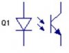
I wish to use opto-isolators in my circuit, though i am sure infra-red LEDs and sensors would do the same job. The circuit symbol of the sensor that works in Circuit Wizard is below.
Since the circuit simulator i have to use is Circuit Wizard, the PICs i can use are any GENIE PICs, but only GENIE PICs.
For more details, visit Welcome to GENIE
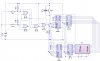
I wanted to do something like the attachment below for the slots, with the sensors behind the holes. However, you said that i could use one sensor to simply calculate the value of the coin. How would i do that????
hi,
I have registered with Genie and will download their design studio, I will look thru and try to determine which range of PICs they are using, to see how we can proceed.
I will let you know if its possible.
Off the record, I think that Genie home page is the worst I have ever seen on the web.!
EDIT:
Downloaded and installed, post your 4029 counter files so that I can run a test.
EDIT2:
The Genie requires a special micro pcb to run.! So its not possible for me to help by using the Genie software.
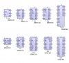
The PICs they have to offer are seen below in the attachment.
What you must know is that the top row are microcontrollers, and the bottom are DILs.
How these PICs work are on a flowchart basis, which may be what you have downloaded.
The micro PCB thing you were talking about may be the software Circuit Wizard. However, this program is not free to download unfortunately.
Is there any other way to detect coins?
Or go back on my original idea, which was to use 8 opto-isolators to detect a coin through special sized slots, which give an input into the PICs and then make a flowchart to output a certain amount of pulses depending on the input?
Note: There is no point uploading my [Circuit Wizard] circuit file as you do not have it. If you are able to come across it somehow, please state so and i shall upload it.
hi,
That Genie name only is a problem.
Commercial cash operated machines have a module which can detect a coins value and also if a coin is counterfeit, they are expensive.
But as you want to detect only genuine coins you should be able to make a mechanism which would be able to detect a coins diameter and weight.
Can you explain how you thought the 4029's counter was going to solve the coin counting problem.?
This site uses cookies to help personalise content, tailor your experience and to keep you logged in if you register.
By continuing to use this site, you are consenting to our use of cookies.