Electro Tech is an online community (with over 170,000 members) who enjoy talking about and building electronic circuits, projects and gadgets. To participate you need to register. Registration is free. Click here to register now.
Welcome to our site! Electro Tech is an online community (with over 170,000 members) who enjoy talking about and building electronic circuits, projects and gadgets. To participate you need to register. Registration is free. Click here to register now.
I'm back with some news : i tried to understand why Pommie's code is fully working with 18F4550 and same code ported to 18F2620 won't display anything.
Actually i found a partial response to that problem :
In order to have something displayed with 18F2620 code, ww variable must be set as ROM char :
Code:
unsigned [COLOR="Red"]rom[/COLOR] char ww;
Doing this gets results with 18F2620, now something is been displayed,
but there are sliding pixels and lagging issues, so it is a very bad display.
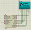
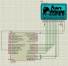
Here are screen captures of Pommie's 18F4550 code result when passing "ww" has rom char , and when setting ww as a regular unsigned char :
Code:
unsigned char XPos,YPos, ww;
( i of course get the same results if i use 18F2620 )
So in order to recap a bit,
here is the comparaison of results i got when using : 18F4550 vs 18F2620 :
18F4550 displays properly when using ww as normal unsigned char.
18F2620 displays nothing when using ww as normal unsigned char.
18F4550 displays badly when using ww as unsigned rom char.
18F2620 displays badly when using ww as unsigned rom char.
So we can say that the problem comes in when the code return ww.
then something gets wrong inside Pic memory ...
Maybe we need to copy ww from ROM to RAM and then proceed the loop, i don't know how to do that ...
You cannot have variables in ROM. ROM stands for READ Only Memory. I just checked your code and dat is a ROM variable.
Code:
unsigned char i;
unsigned char XPos,YPos;
[COLOR="red"]unsigned far rom char dat[/COLOR];

unsigned char GLCD_Read(void){
        b_GLCD_E=1;
        Delay();
        [COLOR="red"]dat[/COLOR]=GLCD_Data;  [COLOR="red"]//dat will never get written to[/COLOR]
        b_GLCD_E=0;
        Delay();
        return [COLOR="red"]dat[/COLOR];
}
This will result in GLCD_Read returning 0xff all the time. This would explain the result you are seeing.
Ok, but how we should explain that "ww" or "dat" ( depends name of variable used ) is getting problem to be returned when using a different Pic familly ?
I tried 18F2620 and also 18F97J60 and i get the same.
I think return dat is not working properly .
Is there a way to change the code and write differently the funtion GLCD_Read(void) that returns "dat" ?
unsigned char GLCD_Read(void){
unsigned char localdat;
        b_GLCD_E=1;
        Delay();
        localdat=GLCD_Data;  //dat will never get written to
        b_GLCD_E=0;
        //Delay();     not needed
        return localdat;
}
But you must also make dat not ROM as it's used elsewhere.
it looks that "GLCD_Data" is not read properly and "ww" not returned ... then rest of the code is not able to display something on the GLCD.
I tryed to put more delays after b_GLCD_E=1; but nothing changed.
It is very strange because Pommie's code works perfectly with Pic 18F4550 but i can't that same code working with any other Pic ( i tried many ones .... )
Can someone post a Demo code working well with a Pic different as 18F4550, then i will compare it to mine and maybe put me on the way to find out the issue ...
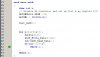
If i understand well, you suggest me to have this in main.c and then run the program in Debug mode in order to read ret variable from Watch windows ?
Code:
void main(void)
{
	char ret,i;
	// disable AD converter and set up Port A as digital I/O
	ADCON0bits.ADON = 0;
	ADCON1 = 0b00001111;

	Init_GLCD();


    for(i=0;i<8;i++){
        SetPos(0,0);
        GLCD_Write_Data(1<<i);
        ret=GLCD_Read_Data();
        if(ret!=(1<<i))
            while(1);
    }
    while(1);
}
Then i run that code ( Release mode in MPLAB ) from hardware and also Prteus simulator, nothing is been displayed on the GLCD .
I"m testing hardware with a lab board, if you want me to test in Debug mode i will have to wire PGC and PGD and MCLR pins ?
That code sets the GLCD with data then reads the data back. Its never supposed to hit the while if the data is reading correctly. Maybe a hardware issue..(meaning wiring or actual GLCD)
You could simply:
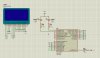
can you post your entire code? like in a zip. I see you were also testing in proteus... can you test current code there as well? Also if you have the proteus DSN file can you post it also. Ill get back to you asap with hopefully a fix! or my own questions heh
Check this out.. if you bypass the wait not busy routine with a normal delay it works fine. I never liked using it heh. Try this out. It has a DSN in it and i replaced your led with actual simulation leds. so you can see then light up heh
Thanks, yes i found too late that my leds were not declared properly.
You are right #define TRIS_Data was not set correctly either.
This would help.
However, i think #define GLCD_Data has to be PORT not LAT because we need to read states, not latches.
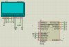
Now, something is coming-in on the GLCD but i'm still not able to display a picture or vertical line, i don't know why ...
It looks that pixels in vertical lines are being lit very slowly and some of them them are missing ...
btw : would you please tell me how you inserted simulator window inside MPLAB i never saw this before, it is a very interresting feature.
This site uses cookies to help personalise content, tailor your experience and to keep you logged in if you register.
By continuing to use this site, you are consenting to our use of cookies.