Continue to Site

Welcome to our site!

Electro Tech is an online community (with over 170,000 members) who enjoy talking about and building electronic circuits, projects and gadgets. To participate you need to register. Registration is free. Click here to register now.

  • Welcome to our site! Electro Tech is an online community (with over 170,000 members) who enjoy talking about and building electronic circuits, projects and gadgets. To participate you need to register. Registration is free. Click here to register now.

Underground wire locator circuit anyone?

Status
Not open for further replies.

Analog

New Member
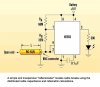
Finding buried cables can be a nightmare. I watched a professional crew use a device that clipped on to the ground of a multi-wire 120VAC underground cable, and injected an 8 KHz signal. The detector device was a hand-held unit that the user swept back and forth to find the peak magnitude of the 8KHz signal through the ground, and thats where he marked it. I estimate the cable was three to four feet below ground. The detector device had an led bargraph to scale the magnitude of the received signal.

He used the same setup to find the phone line, except this time, he clipped the signal generator to the ground shield of the phone cable.

So my question is, does anyone have any idea how this circuit was implemented on the detector side? The signal generator side was battery operated, and coming up with that should be no problem.

I would like to build something like this for fun...

I'm not sure why 8 KHz was used, but it may have been to disassociate with the 60Hz when multiple cables were converging in one location?

Thanks! :):)
 

Attachments

  • Image1.gif
    Image1.gif
    5.8 KB · Views: 1,787
Last edited:
The telephone guy used one of those high-tech expensive gadjets to try fixing my buried phone cable. He dug up cable TV cables and even old car parts but missed the phone cable.
 
Since there is only one connection, it is unlikely that the magnetic field is being sensed. That leaves the electric field, so there must be a low noise, hi gain amplifier for 8 kHz involved. The antenna would be just a capacitor plate and the amp input impedance would have to be high. A bandpass filter for 8 kHz and an LM3914 display completes the set.
 
Russlk said:
Since there is only one connection, it is unlikely that the magnetic field is being sensed. That leaves the electric field, so there must be a low noise, hi gain amplifier for 8 kHz involved. The antenna would be just a capacitor plate and the amp input impedance would have to be high. A bandpass filter for 8 kHz and an LM3914 display completes the set.

When you say one connection, I'm confused. He hooked up a clip from the signal generator to the sheild of the phone cable (for example), and then he had a small grounding rod for the signal generator that was stuck a few feet away into the ground. Would you still consider that electric field?

I would concur with the electric field from a different standpoint, that is, there is effectively no current flowing from the signal generator, since it doesn't see a load on the other end. I.e., its not putting out amps of current, therefore there can't be much (if any) of a magnetic field - what do you think?
 
The amount of current would depend on the conductivity of the soil, so it is unlikely that the current would be sensed. On the other hand, the electric field is between the wire and the conductivity of the ground, so perhaps not much escapes to the air. If the wire is down 4 feet, the uncertainity would be in the order of +- 4 feet. I called Dig Safe once, to find my undrground power lines, they were within 2 feet of being on the money.
 
Russlk said:
The amount of current would depend on the conductivity of the soil, so it is unlikely that the current would be sensed. On the other hand, the electric field is between the wire and the conductivity of the ground, so perhaps not much escapes to the air. If the wire is down 4 feet, the uncertainity would be in the order of +- 4 feet. I called Dig Safe once, to find my undrground power lines, they were within 2 feet of being on the money.

Here is a picture of what I was talking about. Note that the detector is completely floating, no other connection to anything, battery operated. Are you saying that it may detect a small current? Or is it completely capacitive? Or for that matter magnetic?

It had a rounded nose to it, so it didn't look like the old metal detectors. Any ideas?
 

Attachments

  • Image1.gif
    Image1.gif
    5.8 KB · Views: 3,953
I use that type of locators for the POCO to mark out cables prior to fault locating especially on screened 11 and 33 kV cables.
They are Radiodetection, cost about 12,000 NZ$, US$ 8,000.
You can induce a frequency in a cable or cables at 655Hz, 8.1kHz 33.1kHz or 65 kHz. Use different frequencies depending upon length of cable or double check a HV cable prior to spiking.
I prefer as what the telephone guy did, Have the cable disconnected at one end, connect one testlead from transmitter to the screen or outer sheeth, the other to an independant earthpin about 1 meter away.
The cable is usually earthed on the other site and a very accurate location can be done.
A small current at selected frequency is injected in the cable, about 50 to 100 mA. In case of a cable fault or leakage to earth a loss in signal is detected which the receiver will pick up. The receiver has adjustable gain which is visible as a bargraph, or percentage with optional audible sound as well.
When a cable is single core or not screened have both ends disconnected, earth one end and put transmitter at other end with independant earth, so a current at selected frequency can flow.
This method i find better than have the cable acting as an areal and you pick up a lot of other cables as well.
It depends what you are looking for, mark out cables for roadworks or trace the one cable you are interested in.
For cables in service which carry a load to a factory or transformer a clip on CT can be used around the cable, and a current loop can be generated in the cable under test to mark out where it goes.
 
Last edited:
RODALCO said:
I use that type of locators for the POCO to mark out cables prior to fault locating especially on screened 11 and 33 kV cables.
They are Radiodetection, cost about 12,000 NZ$, US$ 8,000.
You can induce a frequency in a cable or cables at 655Hz, 8.1kHz 33.1kHz or 65 kHz. Use different frequencies depending upon length of cable or double check a HV cable prior to spiking.
I prefer as what the telephone guy did, Have the cable disconnected at one end, connect one testlead from transmitter to the screen or outer sheeth, the other to an independant earthpin about 1 meter away.
The cable is usually earthed on the other site and a very accurate location can be done.
A small current at selected frequency is injected in the cable, about 50 to 100 mA. In case of a cable fault or leakage to earth a loss in signal is detected which the receiver will pick up. The receiver has adjustable gain which is visible as a bargraph, or percentage with optional audible sound as well.
When a cable is single core or not screened have both ends disconnected, earth one end and put transmitter at other end with independant earth, so a current at selected frequency can flow.
This method i find better than have the cable acting as an areal and you pick up a lot of other cables as well.
It depends what you are looking for, mark out cables for roadworks or trace the one cable you are interested in.
For cables in service which carry a load to a factory or transformer a clip on CT can be used around the cable, and a current loop can be generated in the cable under test to mark out where it goes.

Thanks for the addition... So do these expensive detectors use the magnetic field, or electric field for detection?
 
Analog said:
Here is a picture of what I was talking about. Note that the detector is completely floating, no other connection to anything, battery operated. Are you saying that it may detect a small current? Or is it completely capacitive? Or for that matter magnetic?

It had a rounded nose to it, so it didn't look like the old metal detectors. Any ideas?

The unit we use here is the same to your connections.

Not sure on the Frequency of operation but it uses a Tuned Coil/cap on the Reciever. Than it feeds into a tuned amplifier.

The Recieve signal is Null, Directly above the buried wire, But Increase as you move either side of it.

It Shouldn't be too difficult to duplicate it or build something simular.
And its Definately not worth the money they want for it.
 
An alternative approach is a Reflectometer as often the route of the cable known and this should help pick a good spot to dig.

Faults such as opens, shorts, or mismatches can be precisely located along the length of a cable by using a time-domain reflectometer. This device launches a rectangular pulse toward the cable's end and waits for an echo signal. The time between the start of the pulse and the arrival of the echo is then converted in terms of distance, allowing the fault to be accurately located. An oscilloscope is typically used to obtain the elapsed time reading.

To detect ordinary open circuits along the cable, however, a simple, low-cost 555 timer IC operating in astable mode can be employed. Coaxial cables have distributed capacitances per unit length, which may be used to replace an actual capacitor (see the figure).

The LED will blink at a rate inversely related to the length of the cable, or at a frequency = 1.443/[(RA + 2RB)C]. For a 45-meter RG-58/U cable, the LED will flash at f1 = 1.67 Hz. When an open circuit is introduced at L2 = 25 meters from the IC, the LED will blink at about f2 = 3 Hz. By observing the increase in the LED's flash rate, the location (L2) of the open-circuit can be determined using the formula L2/L1 = f1/f2, where L1 = 45 meters.

For other lengths of cable, the value of RA and RB may need to be modified to find the values that make visual checking possible. Alternatively, the output of the 555 can be sent to a frequency counter for a more precise reading.
 

Attachments

  • New Image.JPG
    New Image.JPG
    78 KB · Views: 6,849
I doubt the normal NE555 will work that well due to the leakage current on the inputs, a 7555 might do though.
 
I would say the magnetic field.
When detecting live cables with the power option e.g. search in 50 or 60 Hz mode, a better route location is achieved when the cable has a load on it.
When injecting the frequency in the cable, it will be magnetic and some RF signal pick up as well.
For exact pin pointing it is inportant that the search coils are in a 90° angle to the cable.
The field around the cable is usually in the form of concentric circles.
 
The Mad Professor said:
An alternative approach is a Reflectometer as often the route of the cable known and this should help pick a good spot to dig.

Faults such as opens, shorts, or mismatches can be precisely located along the length of a cable by using a time-domain reflectometer. This device launches a rectangular pulse toward the cable's end and waits for an echo signal. The time between the start of the pulse and the arrival of the echo is then converted in terms of distance, allowing the fault to be accurately located. An oscilloscope is typically used to obtain the elapsed time reading.

To detect ordinary open circuits along the cable, however, a simple, low-cost 555 timer IC operating in astable mode can be employed. Coaxial cables have distributed capacitances per unit length, which may be used to replace an actual capacitor (see the figure).

The LED will blink at a rate inversely related to the length of the cable, or at a frequency = 1.443/[(RA + 2RB)C]. For a 45-meter RG-58/U cable, the LED will flash at f1 = 1.67 Hz. When an open circuit is introduced at L2 = 25 meters from the IC, the LED will blink at about f2 = 3 Hz. By observing the increase in the LED's flash rate, the location (L2) of the open-circuit can be determined using the formula L2/L1 = f1/f2, where L1 = 45 meters.

For other lengths of cable, the value of RA and RB may need to be modified to find the values that make visual checking possible. Alternatively, the output of the 555 can be sent to a frequency counter for a more precise reading.

Correct me if I'm wrong, but the reflectometer is used to find faults in cables, right? To just find a perfectly good cable, this wouldn't work - correct?
 
Don't have used a reflectometer but have used the dart for pre location in HV cables.
You can see the cable length to the end, and any joints will show up as a little scribble in the pulsed wave.
In general when a fault is in the cable a negative swing is visible.
By means of a cursor you can work out approx distance to the fault.
Then a Baua thumper is used to pinpoint the actual fault. Quite often you can hear the noise where the cable is arcing over. Sometimes ude the headphones and microphones to listen and accurately pinpoint.
This method is used for screened cables when a Ø to Ø fault or Ø to screen fault is present.

A Ø to earh fault can be located with a POPIE detector to within 5 cm accuracy.
 
Analog said:
Correct me if I'm wrong, but the reflectometer is used to find faults in cables, right? To just find a perfectly good cable, this wouldn't work - correct?

Analog, It appears none of these guys are answering your question.

I'm somewhat on holidays right now, But in September I'll try to do up a design simular to the one you were origionally talking about and post it on my website as a project.

Typically these consists of a modulated, 6 to 10 khz frequency transmitter that connects to one end of the wire, as well as an earth ground, Like you show in your drawing.
Basically The Reciever consists of a coil and a Tuned amplifier that drives a meter and/or headphones.
When the Recieve coil is over the wire, the meter nulls and the modulated tone reduces in volume.
 
A relectometer will tell you how long a cable is, where impedence mis-matches are but not direction or depth
 
chemelec said:
Analog, It appears none of these guys are answering your question.

I'm somewhat on holidays right now, But in September I'll try to do up a design simular to the one you were origionally talking about and post it on my website as a project.

Typically these consists of a modulated, 6 to 10 khz frequency transmitter that connects to one end of the wire, as well as an earth ground, Like you show in your drawing.
Basically The Reciever consists of a coil and a Tuned amplifier that drives a meter and/or headphones.
When the Recieve coil is over the wire, the meter nulls and the modulated tone reduces in volume.

Yes, I believe that you are on the right track to what I want. I would be interested in any projects that you may have ideas on in this regard. Thanks, and I look forward to what's in store...
 
Status
Not open for further replies.

New Articles From Microcontroller Tips

Back
Top