Electro Tech is an online community (with over 170,000 members) who enjoy talking about and building electronic circuits, projects and gadgets. To participate you need to register. Registration is free. Click here to register now.
Welcome to our site! Electro Tech is an online community (with over 170,000 members) who enjoy talking about and building electronic circuits, projects and gadgets. To participate you need to register. Registration is free. Click here to register now.
Yeah nice. He must just need to keep in mind the level shifter will need both voltages to power it, 13V power and 3V3 power for example.
Another option if the 13V input isn't super stable, is to use a resistor and 3V3 zener divider. That makes sure you wont get over voltage conditions into your uC at the same time.
This is your data sheet. Start reading around page 52 regarding pin configurations for DIO. Why have a pull up configured? It looks like you want to just detect a presence of about 13 VDC and not measure it. I would eliminate the pull up in the configuration and do as Nigel suggest making a simple two resistor divider.
The AVR data sheet is very specific. The relevant section is below. You are not allowed to inject any current into a port pin configured as an input, and you must clamp the voltage at no more than 0.5V more positive than Vdd and no more negative than 0.5V below Vss, which would mean that the input swing is constrained from -0.5V to +5.5V if the Atmel is operated from 5.0V.
Now there are folks on here who have violated these rules and gotten away with it. Should this be a recommendation that you should do it?
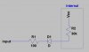
Here is how I would do it:
Note that the voltage is clamped ~+-0.3V using any small Schottky diodes. D2 can be deleted if you know for sure that V(in) will never be negative... You cannot use Silicon Diodes for D1 and D2.
The AVR data sheet is very specific. The relevant section is below. You are not allowed to inject any current into a port pin configured as an input, and you must clamp the voltage at no more than 0.5V more positive than Vdd and no more negative than 0.5V below Vss, which would mean that the input swing is constrained from -0.5V to +5.5V if the Atmel is operated from 5.0V.
Sorry, but that sounds utter nonsense Mike - the AVR was essentially a 'rip-off' of the PIC, which is perfectly happy using a single current limiting resistor and the internal protection diodes (with MANY official application notes showing their use in that way).
You even showed an AVR diagram displaying similar protection diodes, why would you think they are fitted if they aren't of any use?.
But in any case, the two resistor attenuator suggestion I made would easily meet the supposed 'requirements', and at considerably less cost than one resistor and two Schottky diodes
Did you read the data sheet? Did you search ATMEL's web site for applications notes about latch-up? I did. The only reference I could find on ATMEL's site was a caution not to exceed the voltage limits I cited to prevent latch-up. This was in the context of using the SPI where the signal lines are essentially transmission lines, and ATMEL is worried about overshoot/ringing inducing latch-up.
The input protection diodes are there for ESD static protection. Just because a CMOS chip will stand the normal ESD discharge test, that does not guarantee that the circuit will not latch up if it is powered and current is injected into the inputs; two different things!.
If you know apriori that an input signal voltage is limited to say, 0-10V, then sure, you can design a resistive divider that will constrain the pin voltage to keep it within the allowable limits.
Did you read the data sheet? Did you search ATMEL's web site for applications notes about latch-up? I did. The only reference I could find on ATMEL's site was a caution not to exceed the voltage limits I cited to prevent latch-up. This was in the context of using the SPI where the signal lines are essentially transmission lines, and ATMEL is worried about overshoot/ringing inducing latch-up.
So Atmel devices are greatly inferior to PIC's then?
The input protection diodes are there for ESD static protection. Just because a CMOS chip will stand the normal ESD discharge test, that does not guarantee that the circuit will not latch up if it is powered and current is injected into the inputs; two different things!.
I VERY strongly suspect you're worrying about absolutely nothing - but it you consider it a problem?, then perhaps the OP should much to a better made device?.
If you know apriori that an input signal voltage is limited to say, 0-10V, then sure, you can design a resistive divider that will constrain the pin voltage to keep it within the allowable limits.
We know that a PIC is made from high speed Cmos. 74HCxx device datasheets from Texas Instruments have a maximum supply voltage and a maximum input clamp current of 20mA. A note says that the input voltage rating may be exceeded if the input current rating is observed.
Here is what MicroChip says on one of their data sheets. Note that the implication is that the device will not latchUp if the current is limited to +-20mA, however, on another line it says that the pin must be constrained to +0.3V above and below Vdd and Vss, respectively. How can you obey both of these constraints simultaneously?
ATMEL specs only the overvoltage what their inputs will tolerate. Says nothing about current.
Pete, this supports what I have been saying. I worked in the CMOS IC design field in the 80s and 90s, and latchUp was always a huge problem. Seeing circuits that purposely drive CMOS pins above Vdd and below Vss have always make me nervous...
It will be used in car so voltage will be stable apart from some spikes from magnetic clutches etc.
I know about voltage divider what i was wondering is i am using 1mΩ resistor as per attachment to detect zero crossing from 220VAC. So if that works why wont the same can be applied for 13VDC?
I think you mean 1megΩ, not 1mΩ. A resistor that high does not meet the leakage spec on the input pin if the input is swinging from 0V to 12V. With input at 0V, the worst case leakage out of the pin could bias pin to a logic one.
The ATMEL appnote says (on page 4) : The series input resistor is a 1 MΩ resistor. It is not recommended that the clamping
diodes are conducting more than maximum 1 mA and 1 MΩ will then allow a maximum
voltage of approximately 1,000V.
Turning that around, to keep the injected current to less than 1mA, say 200uA, with a 12V input, the resistor should be no less than ~ (12-5)V/0.2mA = 35K.
It is still interesting to me that ATMEL advocates violating an Absolute Max Rating right on their own data sheet.
sorry it is 1megaΩ, thanks for the calculation. So that means i can use a 35-40K and get away with it . But i admit voltage divider is a proper way of doing it.
Pete, this supports what I have been saying. I worked in the CMOS IC design field in the 80s and 90s, and latchUp was always a huge problem. Seeing circuits that purposely drive CMOS pins above Vdd and below Vss have always make me nervous...
It's interesting because there are Microchip Application notes that show designs using the ESD diodes for clamping. The second TB3009 I linked to states in two places that 'passing current through the ESD diodes is outside operating conditions', but doesn't say it shouldn't be done - like saying 'do it at your own risk'.
The first TB3013 is interesting as it seems to imply you will be doing it and then explains the issues and workarounds with the use of external Schottky diodes.
At least when driving a pin above Vdd it would seem to suggest it's okay if you account for the effects it may cause. Driving it below Vss does seem to present more risk of failure due to latch-up.
This site uses cookies to help personalise content, tailor your experience and to keep you logged in if you register.
By continuing to use this site, you are consenting to our use of cookies.