Electro Tech is an online community (with over 170,000 members) who enjoy talking about and building electronic circuits, projects and gadgets. To participate you need to register. Registration is free. Click here to register now.
Welcome to our site! Electro Tech is an online community (with over 170,000 members) who enjoy talking about and building electronic circuits, projects and gadgets. To participate you need to register. Registration is free. Click here to register now.
Always start your files at 20h so the program can be ported to another PIC chip.
You have already been shown how to multiplex two 7-segment displays so that no other chips are needed.
Don't keep going backwards all the time. PIC84's are out of date and expensive. PIC16F628A's are less than $2.00.
Here is a circuit diagram and code using very simple instructions that you be able to understand: **broken link removed** **broken link removed**
Here's the prototype. It took 1 hour to put together and a few hours to write the program: **broken link removed**
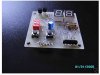
I have a 16f54 PCB which includes 2 buttons, a 2-way DIL switch,
it's on ebay right now (link is on my website)
not a very good design, indeed one of my first PCBs,
but it works, good brightness, and source code for
hex up/down counter, and random numbers is included.
I could even give the source code seperately if interested (just it is explicitely customized to specific PORT bits).
I use plain 2n3904, and no resistors, one 74hc595 buffer.
yes the 16f54 does not have A/D, and also otherwise is limited, only 512 words.
PS. i do not really intend to sell large numbers of this design, it was just an experimental prototype. Indeed, i have made a new design recently.
still have a few unpopulated PCBs around.
money i made out of each PCB was $2 or $3.
Always start your files at 20h so the program can be ported to another PIC chip.
You have already been shown how to multiplex two 7-segment displays so that no other chips are needed.
Don't keep going backwards all the time. PIC84's are out of date and expensive. PIC16F628A's are less than $2.00.
Here is a circuit diagram and code using very simple instructions that you be able to understand: **broken link removed** **broken link removed**
Here's the prototype. It took 1 hour to put together and a few hours to write the program: **broken link removed**
I see, Talking Electronics. it is unrelated to the thread...but...
i know this web site, have played around with some of the dc/dc converter circuits. Recommend, good resource.
You copied portions of my drawing and my example program and posted them on your web site without permission here (under 2-digit up/down counter); 2 Digit up/down Counter
Would you please remove them?
<added 21-Jun-09>
Colin55 (Colin Mitchell) still has not contacted me to ask permission nor has he removed items containing my material from his web site.
reminds me on the SEKA situation on the AMIGA- that assembler was a strong derivation from the standard.
yet it was used frequently, and usually listed LVO's (library vector offsets) at the beginning of the source file, while there have been dedicated include files, for C and also assembly language.
I think SEKA also was some non-profit underground-like tool, you could have it/use it legally without payment.
the really hardcore guys used ANY commercial software they could get hold of.
yes it is unrelated. but would it be possible to use standard include files?
they are available for free from Microchip, you can copy them to the directory of the alternate assembler you are using.
they are just normal text files, available together with MPLAB download.
the spelling encountered here really is not recommended.
If anyone is interested, here's another version of that example program using a single "packed bcd" variable instead of a single "binary" variable (eliminating the need for a bin2bcd routine). This version rolls over from 99 to 00 when incrementing or from 00 to 99 when decrementing but you can implement "hard" limits of 00 and 99 when decrementing or incrementing, respectively, by simply changing two instructions.
The program is reasonably tight and clean and weighs in at a respectable 75 words and 4 variables without any real effort to try and optimize it.
I'll try to post an ISR version with "auto repeat" and "switch press beep" in a couple days.
Regards, Mike, K8LH
Code:
;******************************************************************
;  (C) K8LH 2-Digit Up/Dn Counter, Isochronous Loop Example v2    *
;******************************************************************

        processor PIC16F88
        include "p16f88.inc"
        errorlevel -302

        __CONFIG  _CONFIG1, _LVP_OFF&_WDT_OFF&_INTRC_IO&_MCLR_OFF
        __CONFIG  _CONFIG2, _IESO_OFF & _FCMEN_OFF

number  equ     0x20            ; packed BCD, 0x00..0x99
swlatch equ     0x21            ; switch state latch variable
swflags equ     0x22            ; switch flag bits
DelayHi equ     0x23            ; DelayCy() subsystem variable

#define Dn      3               ; RA3
#define Up      2               ; RA2

;******************************************************************
;
;  K8LH DelayCy() subsystem macro generates four instructions
;
        radix   dec
clock   equ     8               ; clock frequency in Megahertz
usecs   equ     clock/4         ; cycles/microsecond multiplier
msecs   equ     usecs*1000      ; cycles/millisecond multiplier

DelayCy macro   delay           ; 11..327690 cycle range
        movlw   high((delay-11)/5)+1
        movwf   DelayHi
        movlw   low ((delay-11)/5)
        call    uDelay-((delay-11)%5)
        endm

;******************************************************************
;
;  init hardware and program variables
;
        org     0x000
Init
        bsf     STATUS,RP0      ; bank 1                          |B1
        movlw   b'01110000'     ;                                 |B1
        movwf   OSCCON          ; select 8-MHz INTOSC clock       |B1
Stable  btfss   OSCCON,IOFS     ; INTOSC Freq Stable bit set?     |B1
        goto    Stable          ; no, branch, else                |B1
        clrf    ANSEL           ; setup PORT A for digital I/O    |B1
        movlw   b'00001100'     ;                                 |B1
        movwf   TRISA           ; RA3-RA2 inputs, others outputs  |B1
        clrf    TRISB           ; portb all outputs               |B1
        bcf     STATUS,RP0      ; bank 0                          |B0
        clrf    PORTB           ; clear portb output latches      |B0
        movlw   b'00000001'     ; digit select bits (RA1-RA0)     |B0
        movwf   PORTA           ; select the 'ones' display       |B0
        clrf    swlatch         ; clear switch state latch        |B0
        clrf    swflags         ; clear switch flags              |B0
        clrf    number          ; number = 00                     |B0
;
;  isochronous 8 msec program loop (62.5 Hz display refresh rate)
;
Display
        clrf    PORTB           ; blank the display               |B0
        movf    PORTA,W         ;                                 |B0
        xorlw   b'00000011'     ; flip digit select bits          |B0
        movwf   PORTA           ;                                 |B0
        swapf   number,W        ; W = tens in right nybble        |B0
        btfss   PORTA,1         ; 10's display? yes, skip, else   |B0
        movf    number,W        ; W = ones in right nybble        |B0
        call    segtbl          ; get segment data                |B0
        movwf   PORTB           ; display new digit               |B0
Buttons
        comf    PORTA,W         ; sample active low switches      |B0
        andlw   b'00001100'     ; on RA3 and RA2 pins             |B0
        xorwf   swlatch,W       ; changes (press or release)      |B0
        xorwf   swlatch,F       ; update switch state latch       |B0
        andwf   swlatch,W       ; filter out "new release" bits   |B0
        movwf   swflags         ; save any "new press" bits       |B0
CountUp
        movf    number,W        ;                                 |B0
        addlw   7               ; increment + bcd adjust?         |B0
        skpdc                   ; yes, skip, else                 |B0
        addlw   -6              ; increment only                  |B0
        btfsc   swflags,Up      ; Up press? no, skip, else        |B0
        movwf   number          ; update 'number'                 |B0
        movf    number,W        ;                                 |B0
        xorlw   0xA0            ; upper limit 99?                 |B0
        skpnz                   ; no, skip, else                  |B0
        clrf    number          ; reset to 00 (rollover mode)     |B0 <-
CountDn
        movf    number,W        ; lower limit 00?                 |B0
        skpnz                   ; no, skip, else                  |B0
        movlw   0xA0            ; reset to 99 (rollover mode)     |B0 <-
        addlw   -1              ; decrement only?                 |B0
        skpdc                   ; yes, skip, else                 |B0
        addlw   -6              ; decrement + bcd adjust          |B0
        btfsc   swflags,Dn      ; Dn press? no, skip, else        |B0
        movwf   number          ; update 'number'                 |B0
        DelayCy(8*msecs-41)     ; precise 8 msec loop timing      |B0
        goto    Display         ; loop                            |B0
;
;  segment data table (caveat, non-boundary tolerant)
;
segtbl
        andlw   0x0F            ; strip off upper nybble          |B0
        addwf   PCL,F           ;                                 |B0
        retlw   b'00111111'     ; "0"   -|-|F|E|D|C|B|A           |B0
        retlw   b'00000110'     ; "1"   -|-|-|-|-|C|B|-           |B0
        retlw   b'01011011'     ; "2"   -|G|-|E|D|-|B|A           |B0
        retlw   b'01001111'     ; "3"   -|G|-|-|D|C|B|A           |B0
        retlw   b'01100110'     ; "4"   -|G|F|-|-|C|B|-           |B0
        retlw   b'01101101'     ; "5"   -|G|F|-|D|C|-|A           |B0
        retlw   b'01111101'     ; "6"   -|G|F|E|D|C|-|A           |B0
        retlw   b'00000111'     ; "7"   -|-|-|-|-|C|B|A           |B0
        retlw   b'01111111'     ; "8"   -|G|F|E|D|C|B|A           |B0
        retlw   b'01101111'     ; "9"   -|G|F|-|D|C|B|A           |B0
;
;  K8LH DelayCy() subsystem 16-bit timing subroutine
;
        nop                     ; entry for (delay-11)%5 == 4     |B0
        nop                     ; entry for (delay-11)%5 == 3     |B0
        nop                     ; entry for (delay-11)%5 == 2     |B0
        nop                     ; entry for (delay-11)%5 == 1     |B0
uDelay  addlw   -1              ; subtract "loop" cycle time      |B0
        skpc                    ; borrow? no, skip, else          |B0
        decfsz  DelayHi,F       ; done?  yes, skip, else          |B0
        goto    uDelay          ; do another loop                 |B0
        return                  ;                                 |B0

        end
well I see quite a bit of a creep here, the timing macro, which is sort of complicated.
I would like to post my demo code for 2-digit LED display, which includes up/dn counter as program 1, and some random display as program 2, but it goes over 4 or 5 pages.
I always query the TIMER as the subject of the main program loop, so that is synchronized to the clock frequency.
there are no delays!
the proper ratio are derived from additional pseudo-timer-dividers, simple file register counters, together with compare/overflow logic.
All i have to change is the prescaler, if neccessary!
I could post my code if asked for, or put it on a web page in a matter of minutes. I think this one is even documentated.
Hello there,
Can you please send the code for the same circuit(2 digit up down using PIC16F628Aor what ever) for displaying "00" when connected to a potentiometer(10k or what ever) at its least position and "99" at its maximum position.
Thanks and Regards,
Prabhu.R golden_litho@yahoo.co.in
Go to Talking Electronics website and look for the PIC Lab-1 project. It has an A to D code for a pot to 7-segment display. Just connect the pot to an input line and add a capacitor and use the same code.
Dear collin55, thankyou for your help.kindly help me to get output in two digit format(decimal not required).The site has data for only one segment.
Thanks and regards,
prabhu
I have a 16f54 PCB which includes 2 buttons, a 2-way DIL switch,
it's on ebay right now (link is on my website)
not a very good design, indeed one of my first PCBs,
but it works, good brightness, and source code for
hex up/down counter, and random numbers is included.
I could even give the source code seperately if interested (just it is explicitely customized to specific PORT bits).
I use plain 2n3904, and no resistors, one 74hc595 buffer.
yes the 16f54 does not have A/D, and also otherwise is limited, only 512 words.
PS. i do not really intend to sell large numbers of this design, it was just an experimental prototype. Indeed, i have made a new design recently.
still have a few unpopulated PCBs around.
money i made out of each PCB was $2 or $3.
hi !
i am making same circuit as shown above , but i have replaced that Micro Ic Chip and trying to make it with 1 common cathode 7 segment display via parallel interfacing , now what i want its C language Coding if any one have it or any one can make it then plz post here ...... should be many thankful to him!
This site uses cookies to help personalise content, tailor your experience and to keep you logged in if you register.
By continuing to use this site, you are consenting to our use of cookies.