Continue to Site

Welcome to our site!

Electro Tech is an online community (with over 170,000 members) who enjoy talking about and building electronic circuits, projects and gadgets. To participate you need to register. Registration is free. Click here to register now.

  • Welcome to our site! Electro Tech is an online community (with over 170,000 members) who enjoy talking about and building electronic circuits, projects and gadgets. To participate you need to register. Registration is free. Click here to register now.

Tuned LCR circuit for humidifier

Status
Not open for further replies.
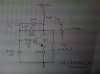
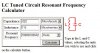
The schematic looks close now. I'm also mystified by the frequency calculations, since I get about 500 kHz with L1 as 60uH or 160kHz with 600uH. If L1 was 6uH the frequency would come out right, but the coil doesn't look that small.

I'm also unable to find a collector bias for Q4.
 
Last edited:
ok, i'm looking at this with a pic of the front of the board, and a mirrored copy of the image of the back.

L3 doesn't need a value, it's a loop for measuring the emitter current using a current probe.

60uh is the correct value for the large inductor 60 and 10E0 for a multiplier (if it were 601, it would be 600uh 60 x 10E1)

the piezo is the resonant circuit and is also part of the feedback circuit and it's what determines the oscillation frequency.

i'll draw this up in SPICE so it makes more sense.
 
Last edited:
60uh is the correct value for the large inductor
I agree, from the markings on the inductor.

The two mysteries to me are (1) 60uH is resonant with 0.0015uFd at 531kHz not 1.6MHz. If C6 was 150pF, then it would make sense.
And still, (2) where is the collector bias for Q4?
 
I would expect that a worthy experiment would be to scale each of (C6 and L1) by 16. That would make C6 = 23nF (make it 22) and L1 = 96uH (make it 1000uH or 1mH). This would keep the impedance in the same neighborhood.

I would also scale the values of L2, C3, C4 and C5. I suspect that these might not be as critical. R13 would not change.
 
i found another schematic for an oscillator, and it only uses 1 transistor. i suspect that Q4 is a clamp of some kind, it gets it's collector voltage from the piezo crystal. in some of these oscillators, the voltage across the crystal can be as high as 200VAC (RF) even with power supply voltages of 50V or less.

the circuit i found has some striking similarities to the one you're working with, and it's design frequency is 100khz. it's configuration is a bit different, as it's a common collector rather than a common emitter. the feedback network is very similar to what you have there. i'll post it when i finish it.
 
I would expect that a worthy experiment would be to scale each of (C6 and L1) by 16. That would make C6 = 23nF (make it 22) and L1 = 96uH (make it 1000uH or 1mH). This would keep the impedance in the same neighborhood.

I would also scale the values of L2, C3, C4 and C5. I suspect that these might not be as critical. R13 would not change.

no, you would scale each by 4, when multiplied by each other the scaling factor would then be 16 (=4*4).
 
I'm at the point that I need to start testing and adapting this circuit. You've both been very helpful, thanks! Any last pearls of wisdom?
 
Last edited:
no, you would scale each by 4, when multiplied by each other the scaling factor would then be 16 (=4*4).
Since the frequency goes as the square root of the product of L and C, you scale each by the frequency ratio.
 
Last edited:
Hi Antknee,
It's funny that I'm studying the same circuit tonight. I can help if you still have questions about it.
 
Hi,
The circuit is based on the classic TDK nebulizer - ultrasonic humidifier. Here is a link to one of TDK's patents that explains the function:
**broken link removed**
Study the Figure 5 schematic. The piezo is kept inductive by tuning the circuit to be below the resonant frequency of the piezo.
Technically the oscillator portion of the circuit is a Clapps Oscillator. See this PowerPoint explanation of oscillator circuits in Colpitts section.
**broken link removed**
The piezo transducer, inductor and the series capacitor are the tank circuit for the oscillator (LC). They set the frequency.
Hope this helps.
 
Here is the schematic for the humidifier circuit that I have here. It is the same as yours.
The piezo transducer resonates at 1.67Mhz. To use this circuit with a 100Khz piezo you can change the following parts:
The inductor Lr (6uH) and capacitor Cr (0.0015uF) form a resonant LC circuit at 1.677Mhz. To calculate the resonant frequency of an LC circuit use this on line resource:

If you change the inductor to 0.53uH and the capacitor to 4.7uF it will resonate at 100,840 Hz (close to your piezo target).
There is a capacitor in series with the piezo that is 0.1uF. This is less than 1 ohm at 1.67Mhz. But at 100Khz the impedence is too high. This needs to be changed to 1uF or greater. Use this on line calculator to check component impedences at different frequencies.
**broken link removed**
This should work fine for you.
Eric
 

Attachments

  • lc-circuit1.JPG
    lc-circuit1.JPG
    40.8 KB · Views: 1,266
If you change the inductor to 0.53uH and the capacitor to 4.7uF it will resonate at 100,840 Hz (close to your piezo target).
530 nanohenries is not a reasonable inductor to use at 100kHz. The impedance of the inductor and capacitor would each be about 0.33 ohms.

As I mentioned before, to keep the impedance in the same neighborhood, it is best to scale both the inductor and capacitor by the frequency difference. The original circuit used reactance values in the neighborhood of 63 ohms. To that end, I still recommend an inductor of 96uH and a capacitor of 22nF. (Subject to confirmation of original devices; since the inductor appears to be marked as 60uH.)

@antknee, can you recheck the value of C6? The circuit would make more sense if C6 was 150pF.)
 
Antknee, please stop deleting your posts when someone's already replied to them.

Even if you've said some stupid stuff, it might not be as silly as you think. Rather than deleting it just own up to the fact that you've made a mistake.


Do you have a data sheet for the new transducer you're planning to use to post?
 
I still recommend an inductor of 96uH and a capacitor of 22nF.

I do agree that your values for L and C are better. I only checked for resonance and not operational reactance.
0.022uF and 115uH resonate at 100,060 Hz and both have a reactance of 72.3 ohms at that frequency.

Yes the original parts values are still troublesome. On my circuit the inductor is marked:
600K so 60uH with a 10% tolerance. The capacitor is marked:
.0015K so 0.0015uF with a 10% tolerance as well.
Parts marking guide:
https://escies.org/escc/specifications/21700.pdf

I'll measure the circuit in operation this week to check the frequency.
Also have a digibridge and will measure the L and C.
Is the diode to clip off half of the piezo drive cycle? or more?
 

Attachments

  • lc-calc.JPG
    lc-calc.JPG
    25.8 KB · Views: 674
Last edited:
Hi eric, mneary. Thanks for your replies.

I've just moved house and don't have internet access at the moment. I did unpack my electronic kit last night and tested some of the capacitors. On the PCB i had different values to the notation. This may be because there is some interaction with the other capacitors. I will take them off the PCB and check them independantly tonight. I'm wondering like you eric if the value notation is well - crap!

For the size of those capacitors i'd be expecting 50-100 nF. Unfortunately I won't be able to reply for a couple of weeks. Why internet service providers in the UK need two weeks is beyond me...

Thanks again.
 
Hi,
The markings are correct. For my circuit:
L1 = 600K marking = 60uH, Measured value = 0.0602mH = 60.2uH
L3 - 1.5 turn of 22 gauge wire with diameter of 7mm, Measured value = 0.0034mH = 3.4uH
C6 - .0015K marking = 0.0015uF, Measured value = 1.52nF = 0.00152uF

Need to cover the piezo with water or it will quickly cook. So that will wait another night (to check the frequency in operation).

Eric
 

Attachments

  • LC-parts.JPG
    LC-parts.JPG
    25.4 KB · Views: 857
Last edited:
Hi,
I was able to power up the circuit this evening and indeed it runs at 1.67Mhz.
See attached screen capture from scope.

Eric
 

Attachments

  • piezo-freq1.jpg
    piezo-freq1.jpg
    41.2 KB · Views: 746
Last edited:
Status
Not open for further replies.

Latest threads

Back
Top