Electro Tech is an online community (with over 170,000 members) who enjoy talking about and building electronic circuits, projects and gadgets. To participate you need to register. Registration is free. Click here to register now.
Welcome to our site! Electro Tech is an online community (with over 170,000 members) who enjoy talking about and building electronic circuits, projects and gadgets. To participate you need to register. Registration is free. Click here to register now.
i am trying to build a digital clock without seconds. so i need to use a 555 to generate 60 hz and connect it to 7493 for minutes. but i could not design it. could any body help me pls.. thanks
The circuit drawn is all with 7490 IC's, because these are easier to get, it may be why your circuit doesn't work.
A 7492 is a 2, 6 and 12 divider. The clock schema is different if you built it with these IC's and you don't need the 7400 gates to divide out the 6.
I see if I can find a 60 counter with those ic's.
'How digital clocks work' (its heavy n ive got a dial up connection).
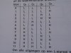
they have got a digital clock made with 7490. mod6 and mod10 u name it. with out the use of any gating circuitry.
I need help with designing a clock with old the 7400 series IC's. I have a 1 MHz crystal "can" oscillator (4-pin).
How can I use this to drive seconds, minutes and hours.
I have tried basic design but it is not working. HELP!!!!!!
If yes, you have to divide the output it to get the 1 Hz frequency .
Inefficient but it works, is to divide it with 6 x 7490 IC's to 1 Hertz. It is probably easier to get a standard 3.2768 MHz crystal and divide it by 16.
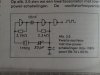
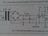
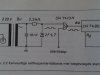
To test your clock use the 50 Hz mains frequency double it via a bridge rectifier to 100 Hz via a small 5 or 6 Volts transformer.
Take off signal via a 1 K 0hm resistor ( I draw you a sketch later , teatime sorry ).
I need help with designing a clock with old the 7400 series IC's. I have a 1 MHz crystal "can" oscillator (4-pin).
How can I use this to drive seconds, minutes and hours.
I have tried basic design but it is not working. HELP!!!!!!
You didn't say what Vcc was for your oscillator, but the attached ckt. will operate OK at both 3.3V and 5V. It's just three cascaded '390's configured for 100 division per with the output at 1 Hz at 50% duty cycle. It should fit the bill.
Thanks for the help but I still have a problem! The canned oscillator I am using will only drive 10 TTL Max. I got it to work the seconds, however, it will not clock minutes.
Is there any way to boost or amplify the crystal's output?
I am using the old 7400 series IC's. Would changing to 74HC work better?
74xxx ICs have a max input current of 1.6mA. 10 have a lot of current.
74HCxxx ICs have no input current. But might not detect a high from a 74xxx.
A 74HCxxx can drive only 2 old 74xxx inputs.
I built the second "ones" hand of a 74LS90 clock.But it seems to be stuck.but if I remove power and plug back in , then it changes.Could somebody advise how to resolve this problem?
My timebase is the 60Hz line from AC mains.I plugged power in, but the leds seems stuck, no counting.They just dont move.It seems like something the preventing the counter from counting.
Could somebody please advise on this problem , Thanks a lot.
never mind my above question, I decoupled all power leads with .1uF and rebuilt the whole thing.I connected leds to QABCD checking for binary out. So it works now . thanks.I still dont know whether It is working right , since I cant read binary!
Decoupling all IC's is a must with TTL. (0.1µF or 100nF ceramic)
The IC's draw small surges in the 5 volt supply during switching which may trigger an input of an other IC hence erratic readings.
As cls tec sais use 74LS90 IC's.
I'm not sure what pete61 means with the canned oscillator ?
The output from the crystal is normally going to the divider and that output normally only drives one TTL gate.
Above is the link for the power supply/timebase I built.The only modification I made is using a 9V-0V-9V transformer and used one side(9V-0V).
So I built some counters to experiment and found that I had to use four decade counters to get it slow enough to get the 0-9 second side.Problem is I dont have enough chips to then get the minute and hour side.It seems like somehow using a 9-0-9 transformer caused the AC line frequency to increase(it should have been 60Hz and I should have to only use 2 chips in divide by 10 and 6 to get 1 Hz and then one more decade counter to get 0-9 second side)
The canned oscillator I am using will drive 10 TTL max (Load). It oscillates at 1 Mhz. I'm using 6 - 74160's to aquire my 1 hz timebase. 2 - 74160's for seconds, 2 - 74160's for minutes etc...
I got the seconds to work, but the minutes stay at zero.
This site uses cookies to help personalise content, tailor your experience and to keep you logged in if you register.
By continuing to use this site, you are consenting to our use of cookies.