Hi all,
I'm hoping someone here is good with wiring electric motors, or maybe knows of a wiring diagram for this motor.
I have come across some new motors that have 7 wires. They are used for raising and lowering overhead doors.
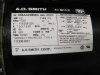
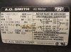
It's a 1 HP reversable single phase motor. The label says Volts 100-120/200-240 Hz 60/50.
The capacitor says 800-960 MFD 110 VAC.
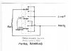
The wires are colored and numbered:
1-orange
2-white
4-yellow
6-black
7-purple
8-red
10-blue
I added a link to pictures of the motor, wiring, label and capacitor.
There is nothing on the motor about wiring.
I'm not sure what type of switch to use with them either to reverse the direction.
Does anyone have experience with these type motors?
Thanks much,
polllo
 ,
,
I'm hoping someone here is good with wiring electric motors, or maybe knows of a wiring diagram for this motor.
I have come across some new motors that have 7 wires. They are used for raising and lowering overhead doors.
It's a 1 HP reversable single phase motor. The label says Volts 100-120/200-240 Hz 60/50.
The capacitor says 800-960 MFD 110 VAC.
The wires are colored and numbered:
1-orange
2-white
4-yellow
6-black
7-purple
8-red
10-blue
I added a link to pictures of the motor, wiring, label and capacitor.
There is nothing on the motor about wiring.
I'm not sure what type of switch to use with them either to reverse the direction.
Does anyone have experience with these type motors?
Thanks much,
polllo
,
Last edited: