Continue to Site

Welcome to our site!

Electro Tech is an online community (with over 170,000 members) who enjoy talking about and building electronic circuits, projects and gadgets. To participate you need to register. Registration is free. Click here to register now.

  • Welcome to our site! Electro Tech is an online community (with over 170,000 members) who enjoy talking about and building electronic circuits, projects and gadgets. To participate you need to register. Registration is free. Click here to register now.

Transmission line.

Status
Not open for further replies.

alphacat

New Member
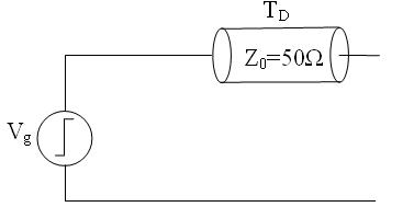
In our class, we described the voltage and the current across/in a transmission line as the sum/difference of progressing wave and regressing wave:
I(z,t) = I+(z,t) - I-(z,t)
V(z,t) = V+(z,t) + V-(z,t)
And that:
I+(z,t) = V+(z,t) / Zo
I-(z,t) = V-(z,t) / Zo
(Zo is the characteristic impedance of the transmission line).

In the bellow picture, I calculated I(z,t) and V(z,t) for t->∞.


V(z,t->∞) turned out to be equal V-(z,t->∞) = Vg (a regressing wave) which makes sense since in the steady state (t->∞), there is no voltage drop across the line.

But it turns out that (according to the above formulas):
I(z,t->∞) = -Vg /Zo.

How come there's current through the line, in steady state (t->∞) ?

Thanks.


tranmission-line-jpg.31458
 

Attachments

  • tranmission line.JPG
    tranmission line.JPG
    6.1 KB · Views: 675
Last edited:
In AC circuits, most notably at frequencies where the transmission line is a significant part of a wavelength at that frequency, current may flow in one part of a circuit while not in another part of the same simple circuit. For example, in your sample the end of the transmission line is open circuit. At that precise point the current is zero. However, as we move a distance away from that point, back towards the generator, the current is no longer zero. The current amplitude begins to increase as we move away from that point. When we reach a distance of one quarter wavelength from that point, the current amplitude is at a maximum and begins to decline. So the current in this case has an amplitude along the line that is the shape of a sinusoid. This is so because you have a Standing Wave along your transmission line. In other words, the incident current going toward the end of the transmission line, and the reflected current coming back from that point, sum together and form a static pattern of amplitude that is this standing wave.

This would not be so in a DC circuit because DC current cannot flow across the open circuit at the end of the transmission line. But in AC, current can vary with distance along the transmission line because the current is flowing at nearly the speed of light.
 
I see, thank you very much for your great answer. :)

I was hoping that you could give me some guide lines regarding analysing the next circuit (i'm new to this material).

I know how to analayse a similar circuit, only without Loop #2.
When integrating both Loops (#1 and #2) in one circuit, i dont know how to analayse it.

My question is this:
At t=Td=2nsec (The Td of the left transmission line), the wave hits R1 - one part this wave withdraws back to the generator, and I dont know what happens to its second part which doesnt withdraw.

If there wasnt Loop #2, i'd say that the second part is absorbed in R1.
But since Loop #2 exists, i'm not sure if the second part of the wave progresses towards R2 or is absorbed in R1.

Thank you very much again.
Regards.


transmission-line-jpg.31488
 

Attachments

  • transmission line.JPG
    transmission line.JPG
    11 KB · Views: 589
Last edited:
I'm a bit rusty with this sort of theory, but I believe it would go like this...the power that couples into the first transmission line travels along until it hits R1. At that point some current would flow in R1, equal to the instantaneous voltage at the point divided by R1, and so some power would be dissipated as heat in R1. Some power would also flow down the second line. The amount of power that launches down this line will be a function of the instantaneous voltage across R1, divided by the characteristic impedance of the second line. After 1 nSec, the power hits R2 where some is absorbed (again, a function of instantaneous V (squared) divided by R2. Because there is a mismatch between the value of R2 and the characteristic impedance of the second line, some power is reflected back down the second line to R1. At R1, the same sort of thing happens in reverse. some of this reflected energy is disappated in R1, some continues to travel towards the generator and some is re-reflected back to R2.

At any point where you have an impedance mismatch, some power goes into the load and some power is reflected back to the source. The "load" in the case of this sort of problem consists of the resistance at that point in parallel with the thevenin equivalent impedance of the next loop to the right, in parallel with that resistor. However, since we are dealing here with a wavefront resulting from a step or non-continuous change in the source voltage (like a pulse for example), the thevenin equivalent impedance of the second loop depends on time. At t=2nSec, the impedance looking into the second loop appears to be just the characteristic impedance of the second tx line. I think.

I'm more used to steady state AC circuits and in those types the circuit could be reduced using thevenin's theorem, so that the second loop is simply a lumped impedance in parallel with R1 and from that it is easy to calculate the effect of current in the first loop. But in this example, where we have a single change in DC level we have to look at things varying with time and in that case, I think my approach above is correct.
 
In AC circuits, most notably at frequencies where the transmission line is a significant part of a wavelength at that frequency, current may flow in one part of a circuit while not in another part of the same simple circuit. For example, in your sample the end of the transmission line is open circuit. At that precise point the current is zero. However, as we move a distance away from that point, back towards the generator, the current is no longer zero. The current amplitude begins to increase as we move away from that point. When we reach a distance of one quarter wavelength from that point, the current amplitude is at a maximum and begins to decline. So the current in this case has an amplitude along the line that is the shape of a sinusoid. This is so because you have a Standing Wave along your transmission line. In other words, the incident current going toward the end of the transmission line, and the reflected current coming back from that point, sum together and form a static pattern of amplitude that is this standing wave.

This would not be so in a DC circuit because DC current cannot flow across the open circuit at the end of the transmission line. But in AC, current can vary with distance along the transmission line because the current is flowing at nearly the speed of light.

Hey,
I gave some thought about it and was wondering, is there a possible way to measure that AC current that flows in the transmission line?
 
Yes indeed. You can do this with an RF current meter or RF current probe on some transmission lines (like balanced open wire lines). With coaxial transmission lines it is a bit more difficult and I'm not sure how it would be done. It is quite common to measure power flow in coaxial lines and if you also measure voltage with a voltage probe then current can be calculated.
 
Status
Not open for further replies.

Latest threads

New Articles From Microcontroller Tips

Back
Top