Continue to Site
Follow along with the video below to see how to install our site as a web app on your home screen.
Note: This feature may not be available in some browsers.
If you want good audio then you should use an opamp instead of a transistor. Transistors were used as preamps or audio filters 50 years ago before opamps were available and their distortion is fairly high. Opamps produce such low distortion that it is difficult to measure any. But do not use an LM324 or LM358 opamp because their low power design causes very bad crossover distortion and noise.
The noise spec's for the transistors are all with different supply voltages, different frequencies, different currents and different source resistances so you cannot directly compare them. Many of the transistors have a HUGE range of noise so some are low noise and others are very noisy.
The BC549 is a BC547 or BC548 SELECTED for its low noise. With the other transistor you are gambling that you might get a low noise one.
I'm sorry, but this is completely false. Semiconductor diodes start conducting at zero volts, and the current to voltage relationship is a power law. The forward voltage Vf (also falsely referred to as turn-on voltage) is simply the voltage drop across the diode at a specified current (often 1 mA), which is often well higher than RF signal levels which can still be detected. So, relying on Vf values is misleading.
Many weak radio signals are less than the typical Vf of a diode, but the diode will still detect the signal.
While Vf does give a vague indication as to whether a diode may be suitable as a detector, there are other more important parameters that determine how well it will work for weak RF signals, (signal levels well below Vf).
The correct theory of diode detection is given here by the late Ben Tongue:
**broken link removed**
I've built a number of crystal sets, and found that the 1N5711 is a very poor detector. There are much better schottky diodes made for detector use, but the best one will depend on the characteristics of the rest of the circuit. It's an impedance matching issue. To get the most audio out, the detector has to be impedance matched to both the RF tuned circuit and the audio output device. The 1N34A is still just about the best there is for the typical crystal set, and they can still be found with modest effort.
 , only 2 ne5532
2n3904 low noise when used in preamp? I have some opamp but they are lm358 and lm324
Simply read the datasheet: 2N3904 at the voltage, current, source impedance and frequency band listed, its noise is typically 5dB but no maximum is given, it might be 20dB which is very bad. A BC549 has maximum noise that is less at 4dB, its typical noise is much less which is very good.2n3904 low noise when used in preamp? I have some opamp but they are lm358 and lm324
I'm sure you have, but maybe didn't realize. A typical 1N4148 behaves this way, but IV curves on typical datasheets tend to emphasize high level signals, and the low voltage behaviour is hard to read. However, have a look at the attached sample IV curves. You'll note that even with the voltage below the so-called VF, there is still current flow.(1) Semiconductor diodes start conducting at zero volts.
I have never seen one of those, and besides which it seems to contravene the band gap physics. Could you show a graph of Vf/If for the diodes you have in mind. Having said that, if there is such a diode in your field of speciality, it would be great to know more because it would open up all sorts of possibilities in circuit design- I mean that. Are you thinking of leakage current?


I guess it would have been more correct to say that it is an exponential relationship rather than power law. I was referring to the Shockley diode equation:(2) the current to voltage relationship is a power law.
I don't understand the term 'power law' in relation to this thread- do you mean the exponential relationship of the Ebers–Moll model? Because, if so that clearly gives a point that could be considered a turn-on. Also I said quite early on that the xtal radio performance could be much improved by matching the antenna signal to the Vf/If diode characteristics, and suggested the use of a matching transformer. Or do you mean power as in watts? I have seen that in micro wave literature
I'm not sure what you mean by cut-off point. I seems that you are still arguing that there is some positive voltage below which there is no current flow. However I refer back to the original quotation of yours which set me off in the first place:(3) The forward voltage Vf (also ... referred to as turn-on voltage) is simply the voltage drop across the diode at a specified current (often 1 mA).
This is one of those basic kick off misinterpretations. Vf is the forward voltage of a diode. The turn-on voltage is one particular value of Vf. They are not the same thing. In fact, I said, in view of the experiments the guys have carried out, Vf seems to be the important characteristic for diodes in Xtal radios. I do not know why you mention 1 mA unless you mean the point on the diodes If/Vf curve where the diode is modeled and subsequently used as a microwave detector.
That may be the way that detectors are specified in detector diode specifications but that is just one point on the Vf/If graph. If I remember correctly, the diodes are biased with 1mA dc to get them beyond the cut-off point as I call it and also to ensure that they are operating at the point that the manufacturers have characterised. But in the case of microwaves a whole load of other characteristics are dependent on bias current. Almost none of them kick in at the frequencies being discussed in this thread. Also xtal radios don't have anything like 1mA If. The whole discussion on this thread relates to weak signal detection. See the Vf/If graphs that I posted previously.
Here, you seem to be implying that VF is a fixed parameter below which there will be no detection. I don't know how you could interpret this statement any differently.As has been implied by the other posts, the forward voltage (VF) of the detector diode defines the lowest amplitude signal that will be detected. This will not be a gradual thing: below the detector diode VF you will get nothing.
Fair enough. I've given a link to a very good source of information. But if you read the referenced information, you'll see that the author never even mentions things like forward voltage or cut-off etc. He is mainly concerned with saturation current, Is, which is the most influential parameter in determining how well a diode works as a detector. The ideality factor n is also important, but since this parameter doesn't vary much from one diode to the next, it of lesser concern than Is.(4) So, relying on Vf values is misleading.
That is to be established.
By weak signals I mean power levels of less than 10 picowatts, which are still intelligible with a decently designed crystal set.(5) Many weak radio signals are less than the typical Vf of a diode, but the diode will still detect the signal.
I am being serious here: what is a weak signal? How do you relate a weak signal to the Vf/If characteristics of a diode. What is the V/I characteristics if the weak signal. I think by weak signal you mean low power. I suggest that if you had a signal with a power of 1 mW with a V/A characteristic (Z) of 10V at 100uA almost any diode would do a fine job. But if the V/A characteristic were 0.1V at 10mA there would be nothing from the detector.
Primarily saturation current Is, and ideality factor n, as mentioned previously.(6) While Vf does give a ... indication as to whether a diode may be suitable as a detector, there are other more important parameters that determine how well it will work for weak RF signals, (signal levels well below Vf).
Could you let us know what those parameters are, as they relate to the relatively low frequency of AM commercial radio. I used to work in a microwave lab so I may have an idea what you are thinking about. If what I think is true you are talking about diode models at microwave frequencies- a very complicated area. But I have used microwave diodes for other purposes; they are just diodes, although dammed fast. GaAs diodes have an even larger band gap than silicon, but they have advantages that outweigh this.
Fair enough. I wasn't disputing what you had said, just restating it.(7) There are much better schottky diodes made for detector use, but the best one will depend on the characteristics of the rest of the circuit. It's an impedance matching issue. To get the most audio out, the detector has to be impedance matched to both the RF tuned circuit and the audio output device.
That is pretty much what I said. My whole object was to investigate which diodes are best.
I was referring to the headphones, or combination of audio output transformer and headphones.When you say, 'audio output device', I'm taking it that you mean detector or do you mean headphones where the Z of the phones directly loads the detector in a simple xtal radio
I think the crossover distortion is reduced considerably with 2k pullup to 5V in the low current LM358 type.(at the expense of DC power wasted)
Hi all,
Just read all the recent posts- very intresting. Have been on other things including domestic duties. Also someone had this light controller and I spent a long time just trying to figure out the circuit diagram!
Not too strange about the full wave detector sounding no louder than the the half wave, now that I have thought about it: like the eye, the ear has a logarithmic response, so doubling the power is just perceptable (3dB). To sound twice as loud you need 10x the power. I think all that is right. If your Xtal earpiece* is truely voltage driven, as opposed to power driven, the audio power would only double so you wouldn't hardly notice that. On the other hand, if it is power driven like a loudspeaker, the volume would go up 4x. You would notice that. If you use the 32 Ohm earphone you will swamp all effects out with the low impedance. Could I suggest staying with the xtal phone for the time being. We can do a hifi version, once the front end detector is sorted. (* appears to contradict physics but the low coupling efficiency, about 3%, is the cause)
If I remember correctly, the full wave detector should have less noise though, for a given signal, that is because the wanted signal is coherent and the noise is just er... noise. I think the noise improvement is around √2. No, doubt the experts will will be able to advise on this if I have got it wrong.
To develop the circuit you really net a meter that can handle up to about 500Hz or better still an oscilloscope.
Great idea, were you thinking about useing RF FETS?
I started looking at a switching demodulator using a compartator which is another approach, but not sure how noisy. If it works it should have a threshhold of about 1mv, compared to the about 150 mv for Ge and Schottkey diodes and probably about 100mv for the biased transistor detector. Now that we are allowed to use a power line for the xtal radio, all sorts of approaches are possible.
A front end amp is probably the best way forward. I think the frequecies for AM go up to 30Mhz.
You make me smile- I have done similar experiments way back. I was testing a circuit built with some expensive components (new fangled transistors) and read that the gain went up with temperature so I heated it all up with my mom's hair dryer. The gain sure went up, but so did the transistors. That cost me about 3 months pocket money.
The voltage depends on the semiconuctor bandgap which should decrease fairly linearly with temperature. Have a look at this:
**broken link removed**
What you have probably seen is the nonlinear effects from the bulk resistance ( I think that is the term) , which cloud the issue, more so as the current through the diode is increased. The 1n4148 is a fast diode with low leakage but I think it has a relatively high resistance. The 1N4001 has a low resistance but a high leakage which would also cloud the issue. Try putting less current through the diode: 10uA would be good if you have a high impedence digital volt meter. The emitter base junction of a small signal transistor should be quite good for temperatue measuerements. Try both the base/emmiter junction and then the base/collector junction.
Water can never get hotter than 100 degrees C, it's a pysical impossibility, unless it is pressurised that is (no doubt you know that). What you were measuring, I suspect, was small bubbles of steam.
Nice reading your posts and talking to you all, but need a 48hr day
View attachment 95288
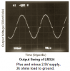
Here is the horrible crossover distortion (it sounds like buzzing) of an LM324 or LM358 opamp with a sinewave as its input:
 Thats some cross-over distortion. Of, course you can always bias the output into class A with a pull up (or pull down resistor) as has been said, but even so they still don't sound good.
Hi again,
Yeah i was really thinking in terms of the commercial AM band which only goes up a little over 1MHz if i remember right. That means we might be able to use a synchronous rectifier and basically design for a variable conduction threshold. Would be interesting to see how this works out.
I meant to mention the bulk resistance too, which is also interesting.
In a practical sense the dc leakage current, and ac noise currents prevent detection at 0V hence a useful forward voltage and current depends on the Noise BW or Q of the front end filter.
I recall designing this single transistor amplifier with over 6o dB of gain BPF at 1MHz for a 50 Ohm loop antenna with an LC band pass filter with very low distortion using negative feedback. using a few mA and running off 1.5V
Here I simulate it with 10 uV of 1MHz sweeping from 0.9 to 1.1MHz you can change the sweep gen to 1m and see how much different V+max out vs V-max for the peak compression difference which is an accurate indicator of THD.
Normally with common emitter you avoid letting Vce get less than 2V for good linearity but with high Q and lots of negative feedback, one can reduce distortion considerable near saturation for Vce =between 0.5 and 2V as shown above.
In a practical sense the dc leakage current, and ac noise currents prevent detection at 0V hence a useful forward voltage and current depends on the Noise BW or Q of the front end filter.
As a favour to Spec...
Here is output of a triangle voltage input is shown on load R as V=I*R
.. neglecting leakage R and diode capacitance and leakage R and noise current , both which limit how high your load resistance can be , hence sensitivity of diode is much less than typical Vf at rated current but much greater than zero. Perhaps 5% of Vf rated@1A is a useful Rule of thumb in 10Meg load range... This affects sensitivity
you can edit any value ( right click) on schematic
or add any node to scope
FALSTAD SIM uses Java may be slow . Stop when not in use.
A pull up or a pull down resistor will eliminate crossover distortion but since the LM324 or LM358 can source twice as much output current as it can sink then the opamp can drive a lower load resistance if the added resistor is a pull down.In fact it's a pull down, Tony. Checked the datasheet.