Hi All,
I'm studying transformerless power supply systems these days and noticed that basically in every circuit I found on internet has a inrush current limiting resistor connected to the supply line where capacitor is not connected.
That is, If the dropper capacitor (and its parallel discharge resistors) are connected to the live, then the inrush limiting resistor is connected to the nutral.
I could only find one legit place that shows a circuit connecting the inrush limiting resistor in the same leg as dropper capacitor, for all other they were using it in the other leg.
Is there any requirement that we "must" add the current limiting resistor to the other leg? logically I dont see why one need to go for the other leg, and doesn't matter if we connect it in either leg, but there could be a reason that I don't know yet")
**broken link removed**
Following is from hackaday, which has resistor in series with the dropper cap
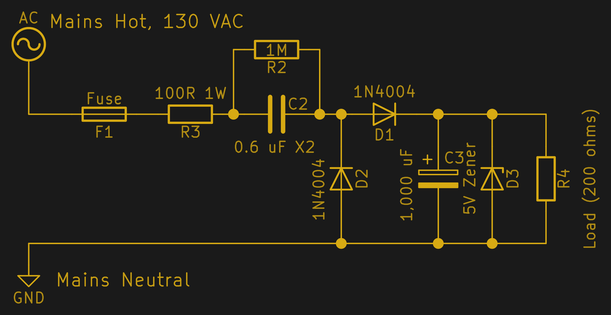
Thank you very much
I'm studying transformerless power supply systems these days and noticed that basically in every circuit I found on internet has a inrush current limiting resistor connected to the supply line where capacitor is not connected.
That is, If the dropper capacitor (and its parallel discharge resistors) are connected to the live, then the inrush limiting resistor is connected to the nutral.
I could only find one legit place that shows a circuit connecting the inrush limiting resistor in the same leg as dropper capacitor, for all other they were using it in the other leg.
Is there any requirement that we "must" add the current limiting resistor to the other leg? logically I dont see why one need to go for the other leg, and doesn't matter if we connect it in either leg, but there could be a reason that I don't know yet
**broken link removed**
Following is from hackaday, which has resistor in series with the dropper cap
Thank you very much
