I have some questions & comments about the circuit attached to your post #14.
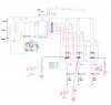
Why is pin 2 connected to Vdd? This is not correct or necessary.
You show 10 rows in your LED tables, such as the one in the post #20 but in the circuit, you have only used 8 of the outputs (not counting O5 ~ 9).
The O & pin numbersa are not aligned with the diode wires.
What colours are LEDs 1, 3, 5, 7, 8, 9?
It is impossible to help you until you correct these issues.
BTW, regarding your post #20 the circuit I posted (see post # 11) was not from a web site. I did the design myself.
Last edited:
") .
.