Electro Tech is an online community (with over 170,000 members) who enjoy talking about and building electronic circuits, projects and gadgets. To participate you need to register. Registration is free. Click here to register now.
Welcome to our site! Electro Tech is an online community (with over 170,000 members) who enjoy talking about and building electronic circuits, projects and gadgets. To participate you need to register. Registration is free. Click here to register now.
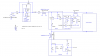
On the input side of the inverters after the 10k resistor I have 5.7v and 2.5v on the output side then it goes into the 47ohm resistor and drops to 0.7v
Yeah, sounds like "fan out". What you want to do is not use the oscillator output directly. Run the output (pin 4) back into another inverter and use the output of that inverter into the parallel inverters and see if the voltage goes up at both points. If it does but not enough, then you may have to spit up the parallel inverters. Try this first though.
On the input side of the inverters after the 10k resistor I have 5.7v and 2.5v on the output side then it goes into the 47ohm resistor and drops to 0.7v
I wonder if that is what's happening if your showing the single gate with that swing voltage at the Exciter ouput "Roff " I'm wondering if I should just drop it down to ( 1 ) gate and see what happens.
If so what would I want to do to the other Inputs and outputs tie them to ground? or float both sides
Run the output (pin 4) back into another inverter and use the output of that inverter into the parallel inverters and see if the voltage goes up at both points.
It would be a good way to test and see if that is the problem which I believe it is. I would also most definitely run the output of the oscillator (pin 4) back into another inverter gate and use it's output to drive the circuit. It's not good to put a load directly on the oscillator without some buffering which adding another gate will do.
On the input side of the inverters after the 10k resistor I have 5.7v and 2.5v on the output side then it goes into the 47ohm resistor and drops to 0.7v
You need to use better punctuation. Does this mean you are seeing 5.7V DC on the input side, 2.5V DC on the output side, and 0.7V DC on the right side of the 47 ohm resistor, or are you seeing AC waveforms?
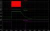
Did you see my simulation? it should be pretty close to what you should see.
You need to use better punctuation. Does this mean you are seeing 5.7V DC on the input side, 2.5V DC on the output side, and 0.7V DC on the right side of the 47 ohm resistor, or are you seeing AC waveforms?
Did you see my simulation? it should be pretty close to what you should see.
Use your scope to look at the output of the oscillator first. Make sure it is a nice 20KHz square wave signal. Next, disconnect everything from the outputs. See if you get a triangle signal. Yes, you should see a triangle signal near 9v pp. The diodes take care of voltage transients on the long cable. If you have those diodes backwards then that is your problem.
I'm seeing a saw tooth now at 6.2v with the diode in the right direction. Now I have 6.2v to 0v oscillation on the output side of the gates after the 47ohm resistor.
I'm seeing a saw tooth now at 6.2v with the diode in the right direction. Now I have 6.2v to 0v oscillation on the output side of the gates after the 47ohm resistor.
Ok, I've been tracing the voltage back and found my other mistake. I have the resistor on Gate of the Mosfet tied to the ground side of the .049 capacitor.
Very Close I can see the 2907 Jumping. A few more adjustments, I made sure I got 2 of everything so if I've damaged it I have the replacement.
Boy, it's hard to do this with so many interruptions. Thats just how it goes around here.
How are you testing this? I would do it first with the exciter (first tested separately, as Dave Johnson recommended) and one sensor and the receiver, all close-coupled (no cables). Make sure you have all the grounds of the 3 circuits connected together.
New measurements I have a fluctuation of 4.5v to 6.5v at the input of the receiver. if I bridge my finger across the Touch Button surface and ground. I have a constant voltage of 2.2v at the Gate of the Mosfet it will reduce only to about 2.1v and then back to 2.2v
No response from the relay yet.
Edit: At this point I did find the Mosfet Leaking. I replaced it.
OK, that brought the voltage up some right? With having a saw tooth wave form you will get a different average voltage than if it was exactly square wave with 50% duty cycle.
WHere does the relay go? To the output of the MOSFET? One other thing you can do to increase the drive (exciter sig.) is to lower the 10K resistor to about 2.2K since the output of the oscillator is now buffered. Try to get that drive up to the full 9 volts peak output and then we work on that receiver circuit which I believe you have connected to the relay.
This site uses cookies to help personalise content, tailor your experience and to keep you logged in if you register.
By continuing to use this site, you are consenting to our use of cookies.

")