Continue to Site

Welcome to our site!

Electro Tech is an online community (with over 170,000 members) who enjoy talking about and building electronic circuits, projects and gadgets. To participate you need to register. Registration is free. Click here to register now.

  • Welcome to our site! Electro Tech is an online community (with over 170,000 members) who enjoy talking about and building electronic circuits, projects and gadgets. To participate you need to register. Registration is free. Click here to register now.

TL084 Output dropping off after a few cycles of input.

Status
Not open for further replies.

Circuit Surgeon

New Member
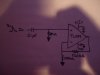
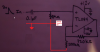
So I've just put together the circuit shown in the attached picture. The idea is to amplify a ~3V trigger to ~5V. The circuit works fine for the first couple triggers, then the output peak voltage starts to fall for subsequent triggers. Eventually there is no output. The only load I have attached is my scope. Any ideas why this is happening?
 

Attachments

  • DSC02347.JPG
    DSC02347.JPG
    257.2 KB · Views: 200
Are you sure the 1 meg is really in the circuit? What voltage does it end up at?
 
The output ends up at around -200mV. And I'm positive the 1M is in the circuit as shown in the pic.

Also I zoomed in a bit, and it looks like the output still follows the shape of the input, but the peak is at like 50mV instead of 5V where it starts out.
 
You might try something smaller than the 1 meg.
What is the driver for the pulse? What frequency? Can you scope the + pin?
 
Is the ground of the input signal connected to the grounds of the opamp circuit and its power supply like this?
 

Attachments

  • TL084 opamp.png
    TL084 opamp.png
    677.6 KB · Views: 175
I watched both supply rails, they're solid. I tried smaller values but that didn't fix the problem and actually caused some attenuation on the input bad enough to negatively affect other parts of the circuit.

The pulse is coming from some DAC I don't recognize, into the common pin of a HD4051 MUX, then depending on which key/trigger is selected it gets connected to one of 8 RC circuits which create a decaying exponential with a time constant of about 200ms and peak voltage of 3.1V. That signal then goes to the base of a npn transistor which acts as a gate for an audio sample. The frequency depends on user inputs/stored patterns, nothing over a few Hz though. Mostly just testing with oneshots.

I'm wiring into the RC networks just in front of the npn bases. Running lines from there to my amplifiers and then to a patch bay for connecting other devices.
 
So based on moffy's input, I added a second 1M resistor between the input and ground (before the capacitor,) and that solved the issue of the diminishing output. Can anyone explain why that worked?

Now I just need to see how much resistance I can add here before the output starts to drop off again, (adding the 1M loaded the pulse source to the point it's distorting the gate.)
 
Since you have a positive DC input pulse that starts at 0V then exponentially decays to 0V then why do you have an input coupling capacitor and 1M resistor?
 
Just remove the cap and 1M resistor and all will be good. DC and caps don't play well together.

Mike.
 
Since you have a positive DC input pulse that starts at 0V then exponentially decays to 0V then why do you have an input coupling capacitor and 1M resistor?
Good point... I had it there whenever I started out using a single supply opamp with a reference voltage above ground. I'd added the cap to remove the negative (wrt virtual ground) DC. Guess I don't need it anymore though. Thanks.
 
Just remove the cap and 1M resistor and all will be good. DC and caps don't play well together.

Mike.
Ok so no problems with removing the cap, but if I take out the 1M resistor between the input and ground then on the next pulse the opamp's output swings up to the usual 5V but only returns to about 4.5V, subsequent pulses peak back to 5V but always returning to 4.5V. I checked the input to make sure there was no DC before or after the pulse, there wasn't. Any idea what's causing the output to sit at 4.5V?
 
Your pulse must be open circuit/3V for you to get that result. What is supplying the pulse? Simple fix - put the 1M resistor back so that no pulse = 0V.

Mike.
 
Your pulse must be open circuit/3V for you to get that result. What is supplying the pulse? Simple fix - put the 1M resistor back so that no pulse = 0V.

Mike.
What does that mean "open circuit/3V" The pulse is coming from some old DAC I couldn't find info on. The DAC generates a relatively short rectangular pulse which goes through a combination level converter/mux and then into one of 8 RC circuits (depending on the trigger used) and finally to the base of a npn. I'm tapping into the pulse circuits just before it reaches the npn.

So yeah the pulse circuits aren't open before I tap into them. Close though I guess? Since they're just going to the base of a npn.
 
I'm saying that the pulse doesn't return to 0V but to open circuit or equivalent to an open circuit. If it returned to 0V then your output would be 0V.

Mike.
 
The DAC generates a relatively short rectangular pulse which goes through a combination level converter/mux and then into one of 8 RC circuits (depending on the trigger used) and finally to the base of a npn.
Without seeing a schematic of that part of the system it's hard to judge, but perhaps the 'C' of the RC can charge via the base-emitter junction but can't discharge? An anti-parallel diode across the junction might solve that.
 
Status
Not open for further replies.

Latest threads

Back
Top