Continue to Site

Welcome to our site!

Electro Tech is an online community (with over 170,000 members) who enjoy talking about and building electronic circuits, projects and gadgets. To participate you need to register. Registration is free. Click here to register now.

  • Welcome to our site! Electro Tech is an online community (with over 170,000 members) who enjoy talking about and building electronic circuits, projects and gadgets. To participate you need to register. Registration is free. Click here to register now.

Thermistor and Comparator Circuit

Status
Not open for further replies.
Yeah I know it's kind of overkill but the selection at the store wasn't that great. The 500Vds is a maximum rating so it still should work if only switching 7V, correct? I also have an NTE326 P-channel JFET. Do you think that would be more suitable?
Will do, thanks!

hi,
That JFET is a low current device and is not suitable for that load current.

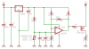
Try the 2381 the P FET, place the heater resistor from the Drain to 0V

The 2381 will switch at 7V ok.
 
Really interesting especially as it is something similar to what I am doing...

MrAl....when replying to messages don't start a new line yourself just keep typing until you really do reach the end of a line and use a full stop. The editor will make the lines the right length.
Sometimes your replies were a little awkward to read with the strange line breaks.

Hi,


I'll keep that in mind thanks. This wasnt a problem with the old interface. Now it seems to be.
 
OK, I made some mods to the circuit in hopes of improving it. I added some caps and a voltage reference as suggested. For the voltage reference, i used 2 NTE952s in series with a 2.2KΩ resistor connected to a +7V supply. The NTE data sheet like most of theirs is pretty crappy. So, I followed the voltage reference example in the **broken link removed** data sheet. NTE952 was listed as a replacement part for the LM336. I also thought it might be beneficial to change the PNP transistor driving the heater to a P-channel MOSFET. Unfortunately, I just got back from my local electronics shop and the closest thing they had to that was a P-channel JFET. I got an NTE326. Does anybody know if this is a suitable component? It was only $1.75 so I figured that if it didn't work I'd just throw it into my stock pile. Updated schematic below. Thanks!

View attachment 38230

Hi,

This new circuit has other problems too. One is that then the comparator output goes low it pulls the supply for the op amp and associated resistors down to around 1/3 of 7v, which isnt a good idea. Maybe a true voltage regulator ic for that instead of zeners?
 
Last edited:
Hi,

This new circuit has other problems too. One is that then the comparator output goes low it pulls the supply for the op amp and associated resistors down to around 1/3 of 7v, which isnt a good idea. Maybe a true voltage regulator ic for that instead of zeners?

I could use a 7805. I have a 100mA output version in a T0-92 package that might work. I also have the standard 220 package ones also. What about increasing the value of the pull up resistor at the comparator output so the supply voltage doesn't get pulled that low?
 
I could use a 7805. I have a 100mA output version in a T0-92 package that might work. I also have the standard 220 package ones also. What about increasing the value of the pull up resistor at the comparator output so the supply voltage doesn't get pulled that low?

hi,
Use the 7805 Vreg, changing the value of the LM pullup will not give the desired result.
 
Hey everyone. I just finished a second round of testing and my circuit is improving. I made some modifications by adding a few onboard caps to smooth out the supply voltage. I also added an onboard 7805 to use as a voltage reference and placed a cap at the output. I also placed another cap on the inverting input line from the thermistor/415 KΩ voltage divider and swapped out the PNP for a P-Channel MOSFET. Last but not least I clipped off the exposed lead to the thermistor and soldered it to some shielded 2 conductor wire so that almost none of the thermistor leads are unshielded. Here’s an updated schematic:

schmitt8-png.38352


The test data showed some interesting results. First off, the problems I had with the first round of testing where the voltage at the inverting input wasn’t getting all the way to the upper or lower set points seem to be corrected. Whatever was causing it before (possibly EMI or RF interference) seemed to be fixed by the shielding on the thermistor leads and/or the extra caps. Also, I wasn’t running my dryer 8 feet away this time either :D 
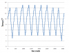
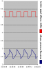
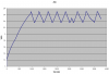
. Here is a plot showing the voltage at the inverting input of the LM293. I’m not sure what that little blip is after the first cycle but after that it’s smooth and consistent. Almost looks like sim data!

273-38322d1264794381-thermistor-comparator-circuit-voltage_test2.png


However, as you can see the voltage jumps that I’m getting whenever the comparator changes output states have not been corrected. This time I did monitor the reference voltage to see what was going on and it was indeed changing. When the comparator output was hi and the MOSFET was not conducting, the output from the 7805 (i.e. reference voltage) was almost 5V exactly but when the comparator output was low and the MOSFET was conducting, the output of the 7805 jumped to ~5.3V. This was at a supply of 8 volts. Just to see what would happen, I varied the output of my bench power supply during a time when the comparator output was low to see what would happen to the 7805 output. When I increased the supply voltage to around 10V, the output of the 7805 raised to ~ 5.35V. You can see the affect this had on the inverting input voltage during the first period when the heater is on. It is labeled as “Supply voltage adjustment”. Can anyone figure out why this is happening?

I also recorded some temp data. The temp is not within my expected range but like I mentioned earlier I question the accuracy of the temp probe on my millimeter. Also, I want to figure out these voltage jumps first and get the circuit working well and then I’ll go start tweaking pots to adjust the range.

274-38321d1264794371-thermistor-comparator-circuit-temp_test2.png


Thanks again for the help everyone.
 

Attachments

  • Temp_test2.PNG
    Temp_test2.PNG
    22.9 KB · Views: 248
  • Voltage_test2.PNG
    Voltage_test2.PNG
    28.6 KB · Views: 228
  • Schmitt8.PNG
    Schmitt8.PNG
    18.9 KB · Views: 725
Last edited:
hi vne,
Will run your 'tested' circuit thru LTS.

I'll look at the test results today, let you know.


EDIT:
Looking at the switching points plot that you posted for the -INV input, a simulation run indicates that the temperature is very close to the -1C thru -5C region, not the +4C thru +14C as your plot shows.

Due to the LM293 design I would expect to see a small change in the -INV input as the +NI inputs switches due the positive feedback created by the hysteresis resistor.

I am concerned about the Source of the P FET being connected to the +8V, while the Gate is connected to +5V [via the 1K]
Using the +8V [Source] as a voltage ref point, the Gate is only changing from -8V to -4V, a 4 volt change.
 
Last edited:
hi vne,
Will run your 'tested' circuit thru LTS.

I'll look at the test results today, let you know.

Hey Eric, thanks for running the sim. I just realized that the schematic in post # 87 had an error. I accidently omitted the 1KΩ resistor in between the LM293 output and the gate of the NTE2381. I corrected the schematic and edited the post so it is accurate now. The resistor I added is R21.

EDIT:
Looking at the switching points plot that you posted for the -INV input, a simulation run indicates that the temperature is very close to the -1C thru -5C region, not the +4C thru +14C as your plot shows.

The temp felt by the thermistor might be much closer the expected range. It is of course impossible for me to place the thermocouple probe from my multimeter in exactly the same place at the thermistor and on top of that I don't know how accurate it is. I wish I was somehow able to tell the exact temp being felt my the thermistor.

the Gate is only changing from -8V to -4V, a 4 volt change.

Should this be the gate is only changing from -8V to -3V? I would think the change would be 5V not 4V. Regardless, can you help me understand why this is a concern?

Thanks!
 
Should this be the gate is only changing from -8V to -3V? I would think the change would be 5V not 4V. Regardless, can you help me understand why this is a concern?

Thanks!

hi,
Look at these images, one shows the Vout swing at the FET Gate the other a modified circuit.

Note the FET Gate threshold voltage, extract from the datasheet.
AAesp02.gifAAesp03.gif
 

Attachments

  • AAesp01.gif
    AAesp01.gif
    8.2 KB · Views: 216
Last edited:
So VGS(th) is the voltage from the gate to the source at which the MOSFET will begin conducting. Correct? When the comparator output is high, the gate voltage is 5V and the source voltage is 8V making VGS 3V which is within the 2V - 4.5V range given in the data sheet. So you are concerned because even when the comparator output is high, the MOSFET is still conducting? Am I getting this?
 
Hi,


You seem to be indicating that the inverting terminal of the op amp is changing when the comparator switches.
Because of this you need to show us a plot of your supply voltage AND the inverting input terminal, on the SAME graph. This is meant to monitor the supply voltage to the comparator (5v supply) while the comparator is switching.

The only things that have control over the inverting input terminal are the supply voltage, the thermistor, and
the input bias current. The input bias current, even if it changed by the entire amount, would only account
for about 0.01 volts at the most. Since the thermistor should not be changing, the only thing left is the
power supply voltage of 5v. If the output load draws down the +8v supply it might cause this.
Of course if there is something wrong with the comparator that would do it too, or something not hooked
up right.

The supply voltage should not be +5.3v at any time. It should be very close to +5v. 5.05 or 5.1 might be acceptable, but
5.3v is not.
 
Last edited:
You seem to be indicating that the inverting terminal of the op amp is changing when the comparator switches.
Because of this you need to show us a plot of your supply voltage AND the inverting input terminal, on the SAME graph. This is meant to monitor the supply voltage to the comparator (5v supply) while the comparator is switching.

Yes, I am indicating that the inverting terminal of the op amp is changing when the comparator switches. I can't show you a real plot of both the supply voltage AND the inverting input because I only have the capabiltiy to record a single measurement at a time. If I were to record them seperately and then overlay the two any differences in on/off time would just make interpreting the plot more confusing and difficult in my opinion.

Here is a plot I doctored to show the effect I'm talking about. The supply voltage (i.e. output of the 7805) varied between 5V when the comparator output was high and 5.3V when the comparator output was low. It is not actual data but I know these were the voltages becasue I measured them real time with a second multimeter (unfortunately one that does not have record capability).

fake-test-data-png.38361


The only things that have control over the inverting input terminal are the supply voltage, the thermistor, and
the input bias current. The input bias current, even if it changed by the entire amount, would only account
for about 0.01 volts at the most. Since the thermistor should not be changing, the only thing left is the
power supply voltage of 5v. If the output load draws down the +8v supply it might cause this.
Of course if there is something wrong with the comparator that would do it too, or something not hooked
up right.

I agree, hence my confusion. I have also checked and rechecked to make sure everything is hooked up correctly and I believe it is.

I did try something else on my bench but haven't done a full up test yet. I tied the source of the MOSFET to the 5V output of the 7805 instead of 8V. Here is an updated schematic:

schmitt9-png.38360


When I did this the inverting terminal of the 293 only changed about 5 mV when the comparator output changed state. That seemed to fix the issue but like I said I haven't done a full up test yet. I'll probably try one later today or tomorrow.
 

Attachments

  • Schmitt9.PNG
    Schmitt9.PNG
    19.5 KB · Views: 717
  • Fake Test Data.PNG
    Fake Test Data.PNG
    10.3 KB · Views: 543
Hi again,


Ok, now we are on to something :)

BTW sometimes if you want to see how the two waves are related in time, you can use two large
value resistors together and at the center tap connect a smaller resistor to ground, then connect
the scope across the smaller resistor and the two inputs one to each large value resistor.
This works if your scope input is high impedance.
What you see is a strange waveform but usually shows how one wave acts in relation to the other.
Sometimes one larger resistor and one somewhat smaller resistors in place of one of the larger
ones makes one wave show bigger than the other, but that gives you just enough information to
figure out the exact timing between the two, then you can go back to one input at a time knowing
the time relation then.
If one resistor is 1 meg and the other is 500k for example, the signal connected to the 500k
will appear to have a greater effect on the total waveform. 1 meg and 10 megs would show
one waveform predominant, with the other riding on top of it, but you would still be able to
figure out the timing from that waveform.
If you have any problem interpreting the resulting waveform, just post a scope shot here
along with the three resistor values you use. Probably making the power supply resistor
much larger than the inverting input resistor would show the inverting input very well
with the power supply square wave riding on it. The resistor to ground should be 100k or
less.

Anyway, now that we know that the power supply is definitely varying, we can look for reasons why
this would happen. Of course the most obvious would be a bad regulator, but another reason would
be (since the voltage goes above 5v) that something in the load is driving it high, or simply that the
load is not low enough to allow proper regulation. The fix is easy, connect a 1k resistor directly
across the output of the regulator.
If it is not that then check to see that the circuit is wired exactly as shown in the schematics.
If anything is different, or some solder short exists, that would surely mess everything up badly
like this.
 
Last edited:
Hello again everybody. I finally got around to doing another test and the circuit is working much better. Adding the regulator definetly helped to attenuate the voltage jumps that are occuring when the ouput changes state but it didn't eliminate them. I'm pretty happy with how the circuit is working. All the measurements are pretty darn close to the predicted/calculated values. Amazing...math works!!!:D And, I'm fairly confident that when I use this circuit in my project and it is not switching a .8A load, it will work fine.

Thanks to everyone who contributed to this thread and worked with me to iron out the kinks. You were all a big help. Here's one last plot of the voltage at the inverting input of the LM293 during the last test. Looks pretty nice to me!

voltage_test3-png.38505
 

Attachments

  • Voltage_test3.PNG
    Voltage_test3.PNG
    14.3 KB · Views: 546
Status
Not open for further replies.

Latest threads

Back
Top