Continue to Site

Welcome to our site!

Electro Tech is an online community (with over 170,000 members) who enjoy talking about and building electronic circuits, projects and gadgets. To participate you need to register. Registration is free. Click here to register now.

  • Welcome to our site! Electro Tech is an online community (with over 170,000 members) who enjoy talking about and building electronic circuits, projects and gadgets. To participate you need to register. Registration is free. Click here to register now.

That "Hello world" OLED moment..!

Status
Not open for further replies.

granddad

Well-Known Member
Most Helpful Member
I added this .96” OLED display to an Amazon order ( To get free postage ) was not expecting a struggle to get that “Hello” moment .
Turns out plenty of device information around just none I could find attached to PIC mcu. I don’t do anything ending in …..uino but I gleaned bits from the various sites to get the hang of the displays control etc.
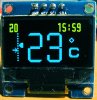
There would appear to be several variations of build, and how the SSD1306 driver chip is is incorporated, not all displays have ready to go I2C standards. I just had to keep trying , I do not use an I2C library . This build will run 3.3 to 5v Vcc , I2C pullups were not required, it has 2 address options , my code shifts address left <1 for w/r bit so starts off at H’3C . Acknowledge of bytes back to master may be a problem , but not with this version. I managed to dump a 5x7 font down the wires (as shown) from a PIC24EP512GU810, These are the init commands that worked for me.
Code:
void Init_OLED()
{
  /*******************WRITE_COMMAND***********************/
      WRITE_COMMAND(0xAE);   //display off
    WRITE_COMMAND(0x20);    //Set Memory Addressing Mode   
    WRITE_COMMAND(0x10);    //00,Horizontal Addressing Mode;01,Vertical Addressing Mode;10,Page Addressing Mode (RESET);11,Invalid
    WRITE_COMMAND(0xb0);    //Set Page Start Address for Page Addressing Mode,0-7
    WRITE_COMMAND(0xc8);    //Set COM Output Scan Direction
    WRITE_COMMAND(0x00);//---set low column address
    WRITE_COMMAND(0x10);//---set high column address
    WRITE_COMMAND(0x40);//--set start line address
    WRITE_COMMAND(0x81);//--set contrast control register
    WRITE_COMMAND(0x7f);
    WRITE_COMMAND(0xa1);//--set segment re-map 0 to 127
    WRITE_COMMAND(0xa6);//--set normal display
    WRITE_COMMAND(0xa8);//--set multiplex ratio(1 to 64)
    WRITE_COMMAND(0x3F);//
    WRITE_COMMAND(0xa4);//0xa4,Output follows RAM content;0xa5,Output ignores RAM content
    WRITE_COMMAND(0xd3);//-set display offset
    WRITE_COMMAND(0x00);//-not offset
    WRITE_COMMAND(0xd5);//--set display clock divide ratio/oscillator frequency
    WRITE_COMMAND(0xf0);//--set divide ratio
    WRITE_COMMAND(0xd9);//--set pre-charge period
    WRITE_COMMAND(0x22); //
    WRITE_COMMAND(0xda);//--set com pins hardware configuration
    WRITE_COMMAND(0x12);
    WRITE_COMMAND(0xdb);//--set vcomh
    WRITE_COMMAND(0x20);//0x20,0.77xVcc
    WRITE_COMMAND(0x8d);//--set DC-DC enable
    WRITE_COMMAND(0x14);//
    WRITE_COMMAND(0xaf);//--turn on oled panel
 
}
OLED1.jpg
 
The OLED is now a seven segment display… ( 4 x apx .3” height ) I have a smart thermostat in mind, so a colon , degree symbol , C and perhaps a little “flame” will be included , also as the digits are at 90 degrees I will try to make the 7 look better, and the 1 offset from the right side, each digit is merged (ORed) into a 4 x 6 frame ( 64 bytes per frame ) there is a spare led page (row) for very small text. The PIC is clocked 30MIPS (will go to 40) and I2C at 400Khz to keep digit refresh reasonable.

Edit ,, added enhanced digits photo.

OLED2.jpg
OLED3.jpg
 
Last edited:
Koolguy , You know I am not sure, simple leds are a version of a fused silicon junction with gallium or similar isotopes , oleds are 'o' organic so presumably are grown rather than fused, this is my first adventure with them, this (point) .96" panel has 8192 oleds so there really small , so I assume also low powered , guessing the same as led tvs only monochrome, this is white , but other colours are available.... it was really cheap <4 GBP from guess where . you need to get your head round the graphical interface SSD1306 to drive the thing.

Edit.... one dot of the colon above is 4 x 4 oleds
 
Thanks for replying.
I just notice the display has good resolution than simple 7 segments.
I mean we can display on it graphics also?
 
Sure it is a graphics device.... I just found it simpler creating a bit mapped seven segment font , a,b,c,d, etc then put them together as required for the digits. then sent the result to the display.
 
Big Thanks for making this! I have been looking at those displays for a while now. They are better looking than the simple 2x16 LCD displays and offer a better range of options. If I follow your command structure Im pretty sure I can port it to Swordfish. I wonder if it would work with hardware I2C, it sounds like you used bit-banging.
 
Overclocked... I'm using the PIC24's I2C HW peripheral, but I have coded my own functions as I could not get on with I2C library , I include the watch dog timer for the possible while( xxx ) deadends. as in the start write.. ( my C would make a programer cry ! )


Code:
void I2C_start_W(char device_addr)
{
         I2C1CONbits.SEN = 1;                                   // Set start bit
         while(I2C1CONbits.SEN){}        //
         I2C1TRN = (device_addr << 1) & 0xFE;                       // send (slave + write bit )
         while (I2C1STATbits.TRSTAT) {}                            //
         I2Cackstat();
}
 
Update... Been back to my central heating programmable thermostat project as i have a Blue yellow OLED still .96" quite pleased with characters , temperature is from mcp7908 clock from mcp RTCC , now adding IR remote for settings , then latching relay for output.

Edit ... Be aware pinout is different from white device, Vdd and Gnd swapped
 

Attachments

  • BY_oled.jpg
    BY_oled.jpg
    435.2 KB · Views: 783
Last edited:
I have returned to this project / display to write a 'print' routine and have developed an ascii 8x16 bit mapped font, currently H'20 - H'5F ( space to underscore) the format uses the OLED controller as a 4 line by 16 Character display , ( 8 line by 16 is too small for me eyes :) ( still not sure about the $ Z & )
Error , the sq brackets should be 5B 5D , the file is correct.


myfont.jpg
 

Attachments

  • Myfont.txt
    7.8 KB · Views: 416
Good work. Even the 6 and 9 can be distinguished upside down. The 2 is a little more difficult, but that distinction doesn't make a difference. ;)

John
 
I found the .96 “ OLED a little small for my Thermostat project, so moved to a 1.3” module , There seems to be several “flavours” of this module available. I got hold of a blue “Waveshare “ for about 6 GBP some weeks ago. It came configured for SPI, so had to move an smd link for I2C, ( H'78 address (3C shifted)) this OLED has a few control differences and more pins. RES... SH1106 controller needs reset low while Vcc is applied , could be done with I/O, but a resistor / cap seems to work . CS... chip select also needs to be low. Other pins as I2C requirements ( with 2k2 pull-ups) . Ran it at 400Khz of a PIC24(16Mhz) The LED panel is a 132x64 matrix, (.96” was 128x64 ) so an 8x16 font has 4 leds not catered for so a tweak on the pixal addresses is required (+2 seems to work ? ). Also the 1106 has only one page mode available so initialization code slightly different . Voltage requirements in documents is a bit vague, so I stuck with 3.3v .

Code:
void Init_OLED() { // for SH1106 control chip
     WRITE_COMMAND(0xAE); // display off
    WRITE_COMMAND(0xB0); // Set Page Start Address for Page Addressing Mode,0-7
    WRITE_COMMAND(0xC8); // Set COM Output Scan Direction
    WRITE_COMMAND(0x00); // Set low column address
    WRITE_COMMAND(0x10); // Set high column address
    WRITE_COMMAND(0x40); // Set start line address
    WRITE_COMMAND(0x81); // Set contrast control register
    WRITE_COMMAND(0x7F); // 0-256 CONTRAST 128
    WRITE_COMMAND(0xA1); // Set segment re-map left 0 to right 127
    WRITE_COMMAND(0xA6); // Set normal/inverse  display
    WRITE_COMMAND(0xA8); // Set multiplex ratio
    WRITE_COMMAND(0x3F); //  (1 to 64)
    WRITE_COMMAND(0xA4); // Output follows RAM content;0xa5,Output ignores RAM content
    WRITE_COMMAND(0xD3); // Set display vertical offset
    WRITE_COMMAND(0x00); //   not offset
    WRITE_COMMAND(0xD5); // Set display clock divide ratio/oscillator frequency
    WRITE_COMMAND(0x50); // Set divide ratio
    WRITE_COMMAND(0xD9); // Set pre-charge period
    WRITE_COMMAND(0x22); //
    WRITE_COMMAND(0xDA); // Set com pins hardware configuration
    WRITE_COMMAND(0x12); //
    WRITE_COMMAND(0xDB); // Set vcom high at deselect
    WRITE_COMMAND(0x20); //  0x20 = 0.77xVcc
    WRITE_COMMAND(0xAD); // Set DC-DC enable
    WRITE_COMMAND(0x8B); //
    WRITE_COMMAND(0xAF); //  Turn on OLED panel
   
    DLYm(10);
    fill_picture(0x00);
}
oled13.jpg
 
Status
Not open for further replies.

New Articles From Microcontroller Tips

Back
Top