Continue to Site

Welcome to our site!

Electro Tech is an online community (with over 170,000 members) who enjoy talking about and building electronic circuits, projects and gadgets. To participate you need to register. Registration is free. Click here to register now.

  • Welcome to our site! Electro Tech is an online community (with over 170,000 members) who enjoy talking about and building electronic circuits, projects and gadgets. To participate you need to register. Registration is free. Click here to register now.

Testing transistors

Status
Not open for further replies.

stuee

Member
Hi, i have a board that keeps blowing a fuse, i cant see any physical damage or blown components which is leading me towards the transisrrs.
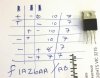
I removed them all and need to know the correct way to test as i tried 2 of 1 kind in diode mode and it all seemed the same (see attachment image)

the ics are
2x F1A26AA
2x FEP16dtd
4x IRFB4019

thanks for any assistance.
 

Attachments

  • 2015-03-02 20.08.28.jpg
    2015-03-02 20.08.28.jpg
    529.2 KB · Views: 224
i just removed the FEP16dtd and tested on diode again and got these results.
I I I
+ - x .450 / .450
+ x - .890 / .890
x + - .450 / .450
- + x OL / OL
- x + OL / OL
x - + OL / OL
 
How can you test transistors without knowing which pin is which and if they are NPN, PNP or Mosfet?
The transistors do not have standard part numbers so you cannot look them up but the IRFB4019 is a standard n-Channel Mosfet that has not diodes to test. its gate-source can hold a charge and give a false drain-Source shorted indication.

You wrote gibberish that might mean something to you but means nothing to me. 0.450 might be the forward voltage drop of a diode but which pins and which polarity?? 0.89V might be the forward biased base-emitter of a darlington transistor, I do not know why you show it twice.
 
Most likely the IRFB4019 N Ch FETS are blown , check for a short on D-S on Pins 2-3 on right.
These are common in Class D kits for $50 ~200W.
 
Last edited:
Just guessing: maybe he is reversing probes? :oops:
No.
A darlington transistor is two transistors. The input transistor has its emitter connected to the base of the output transistor so from the darlington's base to its emitter there are two base-emitter diodes in series. Then with one polarity the two diodes have a forward voltage drop of 0.89V but with the other polarity by reversing the probes both diodes are reverse-biased and do not conduct.
 
i just removed the FEP16dtd and tested on diode again and got these results.
I I I
+ - x .450 / .450
+ x - .890 / .890
x + - .450 / .450
- + x OL / OL
- x + OL / OL
x - + OL / OL
The D suffix is a 30A fast recovery diode pair in series with centre common.
1 ) Anode1 , (left pin down)
2) Cathode1<>Anode2
3) Cathode2

the Spec indicates 0.45V @ 10mA for the 16DT portion of the PN
See Fig 3 . Interpolate the two curves as 16D is in between then minimum Y axis is 10mA = 0.45V
So your test results are exactly as expected.

Again I think it your FETS are blown probably from saturating the core and runaway currents.
 
Last edited:
this is pretty cheap too using the same FETs
250~300 W into 4 Ohms stereo
**broken link removed**
 
Ok thanks everyone for the inputs.
Yes i kinda did mumble a bit at the start.
A few update.
The 2 readings of each is because i have 2 of the transistors etc on the board and was readings from each.

I found a tutorial how to test a MOSFET with a DMM.
I discovered
2 of the 4 Mosfets IRFB4019 gave the correct output from the tutorial and the other 2 failed.
none of the FEP16dtd was faulty
1 of the F1A256AA (which after removing found another number which takes me to a mosfet transistor FQP13N50) was reading bad too.

So i found a supplier in the US that i ordered all new mosfets to replace the lot of them..
Now i wait.
I will keep you upto date when i get them and test :)

again thanks all.
 
Status
Not open for further replies.

Latest threads

New Articles From Microcontroller Tips

Back
Top