Electro Tech is an online community (with over 170,000 members) who enjoy talking about and building electronic circuits, projects and gadgets. To participate you need to register. Registration is free. Click here to register now.
Welcome to our site! Electro Tech is an online community (with over 170,000 members) who enjoy talking about and building electronic circuits, projects and gadgets. To participate you need to register. Registration is free. Click here to register now.
alright, thank you, it is connected to ground, so I will add insulated wire to the speaker outputs. I just assumed that with all of the stereo's that I see, none of them have had insulated wire going from the back of the unit to the speaker. I should stop assuming
alright, thank you, it is connected to ground, so I will add insulated wire to the speaker outputs. I just assumed that with all of the stereo's that I see, none of them have had insulated wire going from the back of the unit to the speaker. I should stop assuming
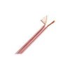
say WHAT????? ALL speakers have insulated wires going from the back of the unit to the speakers.... take a closer look, the wires have clear (transparent) insulation on them..... look closely at the second picture, you'll see what i mean...
Ah, i see, i was recently working with a speaker that had an uninsulated (or what looked like was uninsulated) red and black wire. Thanks for the tip. Does I also need to use insulated wire going from the board to the output connectors that will be mounted on the enclosure, and just use insulated wire from there? I also noticed that when I apply power to the amp, the speaker pulls back, and has to fight to make sound, which is causing the buzzing. Is it the caps and resistors by the speakers that may be improperly grounded? It seems like the signal will go to the speaker then straight to ground with those filters, how can I fix this? I have tried a few things and nothing has seemed to work. I want to take the resistors and caps off to see what happens, but I don't want to damage anything. The resistors seem a little small, could that be the problem? The resistors are the correct value.
Does every amplifier have an input threshold? When I turn the music source volume up past a certain point, the sound from the amplifier begins to distort, before it seems to reach its max volume. This also happens with the smaller lm386 amplifiers i built, is this because it has reached its peak power? Thank you for all of the help.
Does every amplifier have an input threshold? When I turn the music source volume up past a certain point, the sound from the amplifier begins to distort, before it seems to reach its max volume. This also happens with the smaller lm386 amplifiers i built, is this because it has reached its peak power? Thank you for all of the help.
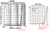
The datasheet for the LM386 shows that when it has a 6V supply and an 8 ohm load it begins to distort (clipping) when its output is only 0.2W which is not loud.
The datasheet for the TDA7240A shows that when it has a 14.4V supply and a 4 ohms load it begins to distort when its output is 15W.
Every amplifier clips (distorts) when its input is turned up too high.
The power into an 8 ohm speaker is shown to be a little more than half the power into a 4 ohm speaker.
The power into 4 ohms with a 14.4V supply is 15W at clipping. It is 20W when the amplifier is clipping very badly with 10% distortion.
The the power into 4 ohms with a 12V supply is 10W at clipping. (Less voltage produces less current which gives less power)
Then the power into 8 ohms with a 12V supply is 6W at clipping.
A manufacturer would rate this mono amplifier at 80 Whats!
That is better then 6, however it still seems to be acting strange, as I turn the pot down, the sound sometimes distorts, is the max input resistance 10kΩ or 100kΩ ? I already increased the main Filter cap to 470uf since it was leaking about 4V of AC before when I checked it with a scope. I also replaced most of the caps to standard electrolytic caps with no axials.
Your hearing's response to loudness is logarithmic so you can hear a pin drop on the floor fairly far away and hear something that is very loud. So twice the power sounds only a little louder. 10 times the power sounds twice as loud.
The TDA7240A has a response up to radio frequencies so it should be made with the pcb design shown on its datasheet. Do not use a breadboard.
C5 should be a 0.1uF ceramic capacitor that is good at high frequencies and mounted with short leads very close to pin 6 and pin 4.
C6 and C7 should be 0.22uF ceramic capacitors that are good at high frequencies and with the associated 2.2 ohm resistors mounted with short leads very close to pin 7 and ground and pin 5 and ground.
The speaker wires must be kept away from the pcb and away from the input cable.
The input cable must be shielded audio cable.
Then the circuit will not oscillate at a radio frequency which causes distortion when you turn down the volume control.
The volume control can be 10k to 50k ohms.
what you have described above is what I have done. I have used shielded wire for all connections going to and from the board. Would it help to use a metal enclosure, that is connected to ground that acts as a large shield, or would that cause problems?
Everything seems to be working fine except for one small problem. I added the second channel by duplicating the circuit. Since I used a 470uf cap as a filter on the first circuit, i added a jumper below the positive cap lead to the second amp circuit, but still used a second .1uf cap as a second filter. When I turned the amp on, the speaker barely moved, which was good, however the first amp still pulled the speaker in. ~2.5 volts were running down the output wires on the first amp, but my meter barely twitched on the second amp. As the second amp started to overheat, I gave it it's own 470uf cap, but then the speaker pulled in when I turned it on. Would it be better to have a large cap right across the leads of the female connector barrel plug? I saw a few comments on another forum of someone using a 4700uf filter cap. I was thinking of using a 1000uf cap, since that was the closest value I had to replace the 2X470uf caps. Thanks for the help, this will hopefully be one of the last comments on this thread.
The value of the filter capacitor on the supply for your amplifier depends on how much ripple is produced by its power supply.
4700uF is good for a stereo amplifier fed from a rectifier that has no other filtering.
The DC voltages for each wire of a speaker are supposed to be exactly the same (at half the supply voltage) so that the speaker has no DC voltage across it.
These IC amplifiers overheat when they oscillate at a high frequency because parts are missing or because the recommended pcb design was not used.
Alright, they have stopped overheating with the new filter caps. Should I still change the two 470uf filter caps for one larger one by the barrel plug, or would that cause more problems. thanks for the help
Alright, they have stopped overheating with the new filter caps. Should I still change the two 470uf filter caps for one larger one by the barrel plug, or would that cause more problems. thanks for the help
Alright. I just didn't see the recommended 220uf cap on the pcb design, so I was not sure if those caps were the problem. There is also a 2 volt difference on the output lines. One of which is ~7 volts, and the other is ~5. Any speculations on what this could be? Since it changed voltages as I switched the 470uf cap, could that be grounded wrong? Does it need to go directly to the ground, because right now they are connected to a small group of other components going to ground. Could that group cause interference with each other? Thanks.
This site uses cookies to help personalise content, tailor your experience and to keep you logged in if you register.
By continuing to use this site, you are consenting to our use of cookies.