Continue to Site

Welcome to our site!

Electro Tech is an online community (with over 170,000 members) who enjoy talking about and building electronic circuits, projects and gadgets. To participate you need to register. Registration is free. Click here to register now.

  • Welcome to our site! Electro Tech is an online community (with over 170,000 members) who enjoy talking about and building electronic circuits, projects and gadgets. To participate you need to register. Registration is free. Click here to register now.

TDA7000 receiver project

Status
Not open for further replies.
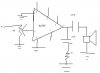
hi again :lol: . i just tried using the lm386, and its even worse than it was. can't hear nuttin. i cant figure out for the life of me wuts wrong, it is DEFINATELY put together right.

I was thinkin though, would it be possible to just use 1 or 2 transistors to make a nice little amp? that way i could save space and would have to play around to get the lm386 workin.
 
Hi Zach,
Please post the schematic of your LM386 amp so we can see what is missing.

If your headphones are very high impedance (unlikely) only a transistor or two will drive them. If they are low impedance, you will need at least 3 transistors and many resistors, similar to an LM386.
 
this is the lm386 schematic from the data sheet.

i think that my headphones may in fact be high impedance because wen i plugged them directly into the tda7000 output coupled through the .1uf cap, i could hear just good enough to make out the words and the songs. The output is 75mv.
 

Attachments

  • 20_gain_lm386_192.jpg
    20_gain_lm386_192.jpg
    20.4 KB · Views: 1,375
Hi Zach,
Your LM386 should work fine if its 0.05uF cap is ceramic and if it and the 10 ohm resistor are connected very close to pins 4 and 5. Pin 6 should have a ceramic decoupling cap to pin 4 also connected close.

Can you measure the resistance of your headphones? It will be just a little less than their impedance.
 
Yeah, your headphones are fairly low impedance and are like a dead short to the output of your TDA7000 circuit. You need the LM386 power amp which matches the impedances properly and provides gain.
 
i am soon gunna make this tda7000 circuit. will this work for european reception? and is it ok to have a telescopic antenna there? and is there any way to improve sound reception? and hwill the FM band be properly recieved in london?
 
look i think on page 4 of this posting, audioguru gave a good explanation as to wheteher or not it will work well in Europe vs. america.

u dont need that 10uf across pins 1 n 8 on the lm386. have a look @ the lm386 data sheet and use the 20 gain circuit. it should work fine.

you can use a telescopic antenna, (or you could design it to work with both) but if this is going to be a radio that you use at your house a lot and you need good reception, have a look at this page, i made that antenna, and it works very well. its around 8 ft. high for 100 MHZ. **broken link removed**
 
Hi Zach,
I don't know where I discussed TDA7000 output level and amplifier gain requirement, but GST Genesis will use it in London.
On their datasheet for the TDA7000, Philips spec's an output level (which I assume is RMS) of 75mV, with a modulation of only 22.5KHZ.

In North America, full modulation of an FM station is supposed to be 75KHz (but the stations seem to exceed it most of the time, more like 100KHz). So we certainly don't need a gain of 200 from the LM386 over here.


Hello Nigel,
What FM deviation is full modulation of your FM stations?
Is it really only 22.5KHz?
 
audioguru said:
Hello Nigel,
What FM deviation is full modulation of your FM stations?
Is it really only 22.5KHz?

From what I can remember it's about 75KHz, certainly not anywhere near as low as 22.5KHz - that's pretty well NBFM (Narrow Band FM). From what I can remember the 2m amateur band used to be split into eighty 25KHz channels, although it later changed to narrower deviation and 12.5KHz channel spacing.
 
hi audioguru, this is what i was talking about.

Hi Zach,
When they designed the FM broadcast band system, they wanted to have a very quiet background sound level, even better than the fairly low noise (high frequency hiss) that FM provides. So they decided to emphasize (boost) the audio high frequencies when they transmit, then allow the receiver to cut the audio high frequencies back down to normal. When the highs are cut, then the hiss is also cut. The Americans, who started FM broadcasting first, chose an agressive emphasis curve so that the hiss was reduced very much during de-emphasis by the receiver. The recorders and microphones at that time didn't have much high audio frequency level anyway.
Years later, the Europeans decided to broadcast FM too, but noticed that the high audio frequencies frequently overmodulated the transmitter when they were emphasized so much. They realised that recording machines and microphones had improved very much over the years since the Americans developed the system and produced high audio frequency levels that were much higher than the system could support. So they chose a less agressive emphasis curve (less high audio frequencies boost).
Therefore the North American and European curves are different. An American radio will sound muffled in europe, and a european radio will sound too bright in America.
Your radio has the agressive American de-emphasis curve where the high audio frequencies are cut quite a lot. (The datasheet has the european curve). However, your simple transmitter doesn't have any pre-emphasis to balance the sound so the radio will play it very muffled, similar to your home stereo having its treble tone control turned all the way down.

Things are working quite nicely. i cant really test out the range of the transmitter because my TDA7000 is not mobile yet. the only thing that ive been able to do is turn the speaker volume all the way up and walk down the street with the transmitter. i can just barely hear my voice booming as i walk about 100 feet from it. my neighbors probably don't know what to make of it:lol: .

i made this antenna for the receiver. is it any better than the simple speaker wire pulled apart 1/4 wavelength each? its kind of hard to see if there is any difference. **broken link removed**
 
Hi Zach,
Emphasis and its corresponding de-emphasis has nothing to do with a receiver's volume and thefore how much gain its amplifier will need.
It affects how hissy that FM reception will be and the tonal unbalance of the sound if they don't match.

You need a partner (your sister with her scooter?) to help you determine your projects' range, and a cell phone, high-power walkie-talkie or smoke signals to communicate. Of course, you might build a second transmitter and receiver to communicate.

I click on your antenna link but end up at Harry's home page. Which antenna?

The spec's for the TDA7000 specifies 2.3% distortion at full modulation.
That's a lot of distortion for an FM receiver, most have 1/20th of that.
 
its the vpole antenna.

sorry about that emphasis/gain/volume thing :lol:

is there any way to fix the 2.3% distortion?
 
Yeah, I'm sorry Zach, but your transmitter and receiver both have the word "cheap" written all over them. That's why I called them "toys".
 
audioguru said:
Yeah, I'm sorry Zach, but your transmitter and receiver both have the word "cheap" written all over them. That's why I called them "toys".
Not cheap , inexpensive ,right zac.. :wink:
 
Hi Willi,
The toy transmitter has always been cheap. I think that it was the very 1st electronic project that I made when I was a kid in the 60's. Its audio was lousy so I made another using a tunnel diode! I think it worked with negative impedance. It had lousy audio too.

Years ago, when the TDA7000 IC was sold at Radio Shack for $10 or $12, I thought it was too expensive for a toy. Today, it is still cheap but also inexpensive since suppliers are clearing them out because they are obsolete. Didn't someone recently buy a keychain radio for only 2 bucks with one inside? When you figure the cost of the battery and headphones which were included, the IC was free. Cheap and inexpensive.

PS. The toy transmitter was my 3rd project. A tube (valve for the Brits) amp and tube FM tuner kits were my 1st and 2nd.
I think that my 4th project was my tube 'scope kit. I still have it and use it every day. I souped-it-up over the years.
A few years later I souped-up my very 1st colour TV. It lasted for, wow, 25 years. Scrambled pay-per-view? Ha, it was a nice challenge to beat. My old 'scope showed me what to do.

Don't you have a similar experience, Nigel?
 
well i would REALLY like to have a decent receiver. is there ANY receivers out there taht actually work well?????????? (and that arent too complicated to build?)
 
Status
Not open for further replies.

Latest threads

New Articles From Microcontroller Tips

Back
Top