Continue to Site

Welcome to our site!

Electro Tech is an online community (with over 170,000 members) who enjoy talking about and building electronic circuits, projects and gadgets. To participate you need to register. Registration is free. Click here to register now.

  • Welcome to our site! Electro Tech is an online community (with over 170,000 members) who enjoy talking about and building electronic circuits, projects and gadgets. To participate you need to register. Registration is free. Click here to register now.

Tank resonance locator

Status
Not open for further replies.
Tony Stewart
3k~150kHz +/- 2.5% would be good. It would be okay if there are no decimal points.
I first should experiment something because I cannot picture the sweeping in my head right now, in order to get a better idea.
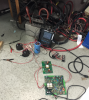
The eventual aim is to make it compact and low power. However, right now I want to try using a current feedback and high power so that I get the idea of how things are working. I can improvise once I get this running. I have figured out the gate triggering and using a ferrite coil CT to test the inverter for now. Then I would see if my frequency is sweeping or not. Once that is figured out, I would look into measuring frequency counter. That is the plan for now.

I appreciate the help. It means a lot.
Vijit.
 
So 2.5% of 3k is +/-75 Hz.
and 2.5% of 150kHz is +/-3.75kHz.
You may as well buy a used counter.
 
I tested the inverter after testing te rectifier independently. I blew it during testing inverter. Troubleshooting for now.
Tony Stewart Is there any way I could build one for this range.
 

Attachments

  • Capture.PNG
    Capture.PNG
    827.7 KB · Views: 190
**broken link removed** you might be able to use this counter, if you can get the PLL to lock during a sweep.

it has 5 digits. but no specs for triggering, averaging, gate time etc.

Make a portable unit, sure it's possible with good specs.

You can't sweep an IGBT bridge into a huge reactive load with 7uF ( I think 120V with 10 mOhm ESR on the Caps ( I think, not 0.5 Ohm) would cause say 150V/0.01Ω = 15000 Amp step current .. poof. neglecting actual Rce of IGBT.
I checked everything, my caps are fine. But I burnt my IGBT and mic-422cn in my gate drive. Could it be due to the ringing created due to the stray inductance of the wires. It was on no load, the output of the inverter was open circuited and it was supposed to work at starting frequency. With no current feedback it was not supposed to change freq. The gate burnt at t=4 seconds.
 
I didn't expect the Cap rated @150KVAR 9600 Hz 562 Amp to blow! I expect the IGBT to blow if not current limited.

I think you need to get an RLC meter. The cap probably is oil filled large inductance and not Plastic low ESL.
 
That cap is not designed for 150kHz induction heating.

It is rated at 9600 Hz only which (my guess ) is probably the series resonant frequency at 562 Amps or it could be used at lower frequencies such as a 1000 HP Induction Motor

That would put the Zo at ~ 1.3 Ohm at 9600 Hz and ESL at 20 uH.

Did you check the resonant frequency of the Cap yet?

What the heck are you trying to accomplish with different coils and that cap?
These capacitor and coils are used in the industry. I'm sorry, something was wrong with my function generator, my resonant frequency is 10K. I tested with a new function generator. As far as I believe, capacitor ratings derate when you go beyond the rated frequency. However, I looked at the charts and I am sure I am in the safe range. I have kept the starting frequency at 33KHz right now.

The idea behind using different caps and coils is to test the range in different frequency. I figured out the problem why the gate driver blew. The deadband was just 400ns. I increased it to 1.2us now. Also I introduced a bleeder across the filter capacitor and a snubber across the DC terminals of the IGBT modules. I would test the inverter in the morning.

Vijit.
 
Parasitic Reactive loads have a way to closing deadband time causing shoot thru.
>1us should be OK in most cases.

Still think you should get a decent RLC meter and measure L, C, Rs , D, Q for each part L and C and cable. Then you can characterize the combination sets easily with an online simulator for frequency response, resonance(s) , loss and optimum impedance match on driver.
After burning 1 IGBT and 1 transformer. I have finally started running on my tank using inverter at 33KHz. The no load voltage output now is 9V AC at 33.1 KHz. The current during clamping it to tank is going around 30A. I am going to get a current feedback using a ferrite coil.

So I guess, inverter issue is fixed now. I have now have to worry about sweeping. I'll start working on the frequency sweep on Monday.
Meanwhile, could you suggest any other frequency counter. The one that you suggested earlier has a late date of delivery (20-40 days). I need something in 3-4 days. Budget- max upto ~$30
 
I know how to design an automated sweep system using constant current sine waves with PWM control into a 0.5 Ohm Series Resonant load between 3k~150k using several Amps from low voltage LiPo batteries ( bipolar). But I dont have time to create the complete design and tell you all the necessary details. It should be a constant current swept frequency with a higher voltage supply available for the best response, but I can lock on with low voltage.

Sample and hold circuits , that I have designed in the past with long time constants using plastic film caps with FET input low bias current OA; with over 1000 sec time constants.

In the past I have done with this a 14 bit CD4060 counter and 12 bit DAC to sweep the VCO and disable the clock to hold the frequency.
To measure now can be done with a PIC but I used 2 more counters, one CD4040 11 bit resolution to count VCO pulses and another with a Xtal time base such as 32kHZ watch crystal to generate 12 second time intervals with the logic to compute the binary end of count to match the Xtal frequency with a switch for 0.1 or 1s intervals. Then you can get away with a binary to BCD 7 seg display or use 4 BCD counters. The CD4040 is a 12 bit counter with 11 bits resolution. for a display from 000.0 to 204.7 or 00.00 to 20.47 ( 2^11)

I have also done quadrature PLL Eddy Current instrument design with 100 ppm resolution of 1 Ohm for both real and reactive impedance, but rather complex at the time.
The reason you should consider this is to measure REAL power generated for induction rather than APPARENT power not just resonant frequency as the no load power needs to be sensed anyways and power will change with magnetic material induced, which ought to be monitored.

I've done quite a few PLL's for Doppler Navigation and high speed data recovery. Another way you can measure phase for these frequencies is using a triangle wave inverted on alternate phases to make a Sawtooth then use the detected signal zero-crossing using an XOR delay comparison, to sample and hold the sawtooth phase with the fastest pulse one shot that an Analog Switch with Plastic Film cap and FET Input Op Amp for low drift. ( never use ceramic unless C0G)

Good luck. your $30 budget and $3000 of my time. Go rent or buy a freq counter .

But if you like cheap **broken link removed**
 
Last edited:
Here's an example of an excellent Freq counter with 1e-10 accuracy. $300 used.
**broken link removed**
 
I know how to design an automated sweep system using constant current sine waves with PWM control into a 0.5 Ohm Series Resonant load between 3k~150k using several Amps from low voltage LiPo batteries ( bipolar). But I dont have time to create the complete design and tell you all the necessary details. It should be a constant current swept frequency with a higher voltage supply available for the best response, but I can lock on with low voltage.

Sample and hold circuits , that I have designed in the past with long time constants using plastic film caps with FET input low bias current OA; with over 1000 sec time constants.

In the past I have done with this a 14 bit CD4060 counter and 12 bit DAC to sweep the VCO and disable the clock to hold the frequency.
To measure now can be done with a PIC but I used 2 more counters, one CD4040 11 bit resolution to count VCO pulses and another with a Xtal time base such as 32kHZ watch crystal to generate 12 second time intervals with the logic to compute the binary end of count to match the Xtal frequency with a switch for 0.1 or 1s intervals. Then you can get away with a binary to BCD 7 seg display or use 4 BCD counters. The CD4040 is a 12 bit counter with 11 bits resolution. for a display from 000.0 to 204.7 or 00.00 to 20.47 ( 2^11)

I have also done quadrature PLL Eddy Current instrument design with 100 ppm resolution of 1 Ohm for both real and reactive impedance, but rather complex at the time.
The reason you should consider this is to measure REAL power generated for induction rather than APPARENT power not just resonant frequency as the no load power needs to be sensed anyways and power will change with magnetic material induced, which ought to be monitored.

I've done quite a few PLL's for Doppler Navigation and high speed data recovery. Another way you can measure phase for these frequencies is using a triangle wave inverted on alternate phases to make a Sawtooth then use the detected signal zero-crossing using an XOR delay comparison, to sample and hold the sawtooth phase with the fastest pulse one shot that an Analog Switch with Plastic Film cap and FET Input Op Amp for low drift. ( never use ceramic unless C0G)

Good luck. your $30 budget and $3000 of my time. Go rent or buy a freq counter .

But if you like cheap **broken link removed**
Thanks for helping so far. Sorry for making you feel that you wasted your time. I'm a partially funded rookie.

Vijit.
 
WHen when I was a rookie and didn't have a Vector Network Analyzer or Bode Plotter
this is how I did it in the lab.

I used a slow sine or sawtooth to Analog Scope Ch1 in then CH1 out on the back to VCO or FM gen. then FM gen to circuit and output V or I sense to CH2 on scope and used XY mode so Ch1 was now X axis and Ch2 was the linear swept envelope response. I could change centre F with CH 1 offset trace adjust and gain with Sensitivity. I could switch Ch1 to Gnd on scope and centre sweep manually with vertical adjust to centre and then ac couple to sweep symmetrically around peak then adjust the circuit to see response changes rectifying would give the linear envelope or frequency response.

Just a FYI.

But this challenge is very low impedance, Q must be 50 for 98% induction efficiency ( otherwise it becomes a conduction heater.)

Like an audio amp, except instead of 4 Ohms, it is 10x smaller impedance load, where dampening factor only means ratio of load to source impedance, where 100 is good , 10 is poor, 1000 is great.
So good means your driver impedance is 5~50 mOhms, including your non-inductive current sensor.

Without a tracking filter, current response has many harmonics for inductive load , unless you drive with a sine wave or pseudo sine. or even a triangle wave would be 12dB better. ( 6db/harmonic or octave))
 
Last edited:
When you used manual method did you use a 50 Ohm generator and get 0.5/50 or 0.1% of the input when sweeping near resonance?

WHen I did your method when I was a rookie and didn't have a Vector Network Analyzer or Bode Plotter this is how I did it in the lab.

I used a slow sine or sawtooth to Analog Scope Ch1 in then CH1 out on the back to VCO or FM gen. then FM gen to circuit and output V or I sense to CH2 on scope and used XY mode so Ch1 was now X axis and Ch2 was the linear swept envelope response. I could change centre F with CH 1 offset trace adjust and gain with Sensitivity. I could switch Ch1 to Gnd on scope and centre sweep manually with vertical adjust to centre and then ac couple to sweep symmetrically around peak then adjust the circuit to see response changes rectifying would give the linear envelope or frequency response.

Just a FYI.
Yes, I believe it was 50 ohm generator and then I used a oscilloscope to see the response and frequency. Even right now I am using oscilloscope to look at frequency instead of a frequency counter.
I was about to order one of those cheap frequency counters for the circuit. But then I tried looking it up on youtube to see if it works and I came across this video:
Do you think it will work with my circuit. Talking about this one (**broken link removed**)

Currently, I have started getting a feedback to my vco and I am working on sweeping it.

Vijit.
 
Yes it should work with limitations.

It is designed to insert a crystal and you can insert a small signal ac coupled to the pin designated as input and the other pin is output of a CMOS inverter classic Pierce Oscillator with some std load capacitance perhaps 10~16 pF. It may need to be AC coupled with a suitable RC time constant and the feedback R of 1~10Meg across the crystal test pins should be internal for self biasing. It should work with a filtered signal that has no glitches from 10mV ~ 1V but glitches or multiple zero-crossings or slew rate drift of DC on the AC coupling will cause errors. So it should be a "clean " spike or signal without multiple transitions and should be driven with coax or twisted pair for EMI immunity with a known source impedance << 1K to determine the RC time constant as the signal sweeps.

If you need more resolution I would suggest using the 4046 and 1/100 decade counters to boost the VCO signal x100 frequency for better resolution. Then you would sweep from 300k to 15Mhz and derive 1/100 the output clock. I would use the 2nd decade counter as a Johnson DAC converter to create a pseudo sine wave using a spreadsheet to compute the Resistor values for SINE values weighted to generate a quasi-sine wave to drive 1Amp constant current into the load which drops to the ESR value of maybe 10 milliohms at resonance, while the impedance of each reactor is around 0.5 to 1Ohms giving a Q of 50 to 100 at resonance and a -3dB bandwidth of only 1 to 2%. If you choose parts with higher ESR or use a current shunt of 50 Milliohms , this drops the Q to 5 or 10, which I suspect is what you did. Then you get 50 mV per Amp and the signal will have 10% distortion, if my estimates are correct and your ESR measurements are wrong.

You can put 1 AMP DC across the coil to measure mV to get ESR. This is important.
It ought to be < 1 Ohm from the photo and use Litz magnet wire cables to drive it for low inductance

The Cap , ESR can be measured using a square wave to drive and measure mV square wave well below SRF The residual square wave will be the internal ESR and cable resistance which should also be very low inductance << ( < 50 pico Henries.) preferrably using Litz wire or many strands of 1mm magnet wire to the same diameter cable used for final product. Not essential for tests now. But don't forget skin effects and parasitic inductance and ESR.

If you apply a square wave into this 592 AMP capacitor, at low frequency, it is essentially shorted out by the Cap ESR. If this tank of oil can dissipate 250 Watts at 592 Amps then I would expect ESR is around 0.5 Ohm like you said. which is very lossy dissipation factor but cheap. Polycarbonate or Polyester rack mounted capacitors are what are used now in industry which can give ESR values < 1 mΩ or very low D factors.

You can read the ESR by the attenuation of the square wave ratio with 50Ω
well below resonance.

A precision RLC meter makes life so much easier for $250 ~$350 and it should last forever. Cheap ones work but with limitations like auto-cal.
 
Last edited:
Yes, I believe it was 50 ohm generator and then I used a oscilloscope to see the response and frequency. Even right now I am using oscilloscope to look at frequency instead of a frequency counter.
I was about to order one of those cheap frequency counters for the circuit. But then I tried looking it up on youtube to see if it works and I came across this video:
Do you think it will work with my circuit. Talking about this one (**broken link removed**)

Currently, I have started getting a feedback to my vco and I am working on sweeping it.

Vijit.
This would be much less prone to errors.
https://www.banggood.com/VC3165-110V-220V-Professional-Precision-Frequency-Counter-p-953036.html and useful for many other activities.
 
This one is cheap but is a DMM with a counter > 200Khz **broken link removed**
 
Yes it should work with limitations.

It is designed to insert a crystal and you can insert a small signal ac coupled to the pin designated as input and the other pin is output of a CMOS inverter classic Pierce Oscillator with some std load capacitance perhaps 10~16 pF. It may need to be AC coupled with a suitable RC time constant and the feedback R of 1~10Meg across the crystal test pins should be internal for self biasing. It should work with a filtered signal that has no glitches from 10mV ~ 1V but glitches or multiple zero-crossings or slew rate drift of DC on the AC coupling will cause errors. So it should be a "clean " spike or signal without multiple transitions and should be driven with coax or twisted pair for EMI immunity with a known source impedance << 1K to determine the RC time constant as the signal sweeps.

If you need more resolution I would suggest using the 4046 and 1/100 decade counters to boost the VCO signal x100 frequency for better resolution. Then you would sweep from 300k to 15Mhz and derive 1/100 the output clock. I would use the 2nd decade counter as a Johnson DAC converter to create a pseudo sine wave using a spreadsheet to compute the Resistor values for SINE values weighted to generate a quasi-sine wave to drive 1Amp constant current into the load which drops to the ESR value of maybe 10 milliohms at resonance, while the impedance of each reactor is around 0.5 to 1Ohms giving a Q of 50 to 100 at resonance and a -3dB bandwidth of only 1 to 2%. If you choose parts with higher ESR or use a current shunt of 50 Milliohms , this drops the Q to 5 or 10, which I suspect is what you did. Then you get 50 mV per Amp and the signal will have 10% distortion, if my estimates are correct and your ESR measurements are wrong.

You can put 1 AMP DC across the coil to measure mV to get ESR. This is important.
It ought to be < 1 Ohm from the photo and use Litz magnet wire cables to drive it for low inductance

The Cap , ESR can be measured using a square wave to drive and measure mV square wave well below SRF The residual square wave will be the internal ESR and cable resistance which should also be very low inductance << ( < 50 pico Henries.) preferrably using Litz wire or many strands of 1mm magnet wire to the same diameter cable used for final product. Not essential for tests now. But don't forget skin effects and parasitic inductance and ESR.

If you apply a square wave into this 592 AMP capacitor, at low frequency, it is essentially shorted out by the Cap ESR. If this tank of oil can dissipate 250 Watts at 592 Amps then I would expect ESR is around 0.5 Ohm like you said. which is very lossy dissipation factor but cheap. Polycarbonate or Polyester rack mounted capacitors are what are used now in industry which can give ESR values < 1 mΩ or very low D factors.

You can read the ESR by the attenuation of the square wave ratio with 50Ω
well below resonance.

A precision RLC meter makes life so much easier for $250 ~$350 and it should last forever. Cheap ones work but with limitations like auto-cal.
Thank you. I would surely consider your suggestions.
My circuit started working and is sweeping now. I'll get a small frequency counter now and make a smaller clamp on tank frequency counter as the project. So far I am using the scope as a frequency counter. I'll order those minute $10 circuit and come up with a small clamp on box which would throw the resonant frequency in display as output.
Thank you so much for guiding me. I couldn't have done it without your help. It means a lot.
Once again, thank you for so many suggestions for a frequency counters.
 
Last edited:
For giggles and kicks I tried to make the tank circuit with an oscillator with <10mΩ source impedance but not consume much power driving the series tank circuit.

It was a bit problematic but it oscillated at resonant frequency. The challenge was to get Barkausen criteria with positive feedback and minimal DC offset into a 50mΩ current shunt with negative feedback for DC operating point and not suck much current. I used +/- 3.7V to DC couple and prevent DC current thru the inductor.

But in the time I spent on it, it wasn't good enough to be reliable for a wide range of LC values.

upload_2015-9-29_14-16-48.png


To make a good sample and hold , you can use CMOS analog switches but low bias FET input OP Amps and low leakage caps ( Plastic film)
 
Status
Not open for further replies.

Latest threads

New Articles From Microcontroller Tips

Back
Top