Hi
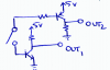
I'm designing a circuit, and there's one little problem. I basically want to have two outputs in such a way that when a push button is pressed, the first outputs switches from 5v to 0v, and the other from 0v to 5v. The restriction is that this can only be activated with that one push button. I can't figure out how to do it, as i am kind of new to electric circuits. i have attached an image of the circuit.
Thanks