Continue to Site

Welcome to our site!

Electro Tech is an online community (with over 170,000 members) who enjoy talking about and building electronic circuits, projects and gadgets. To participate you need to register. Registration is free. Click here to register now.

  • Welcome to our site! Electro Tech is an online community (with over 170,000 members) who enjoy talking about and building electronic circuits, projects and gadgets. To participate you need to register. Registration is free. Click here to register now.

Switching Led

Status
Not open for further replies.
Edited above post.

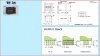
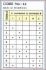
p355 is even better (an excerpt) of some of the important parts.

1. "Max" means the highest value where the pin is guaranteed to be read as low.
2. "Min" means the lowest value where the pin is guaranteed to be read as high.
3. Although each I/O port can sink more than the test conditions (20mA at VCC = 5V, 10mA at VCC = 3V) under steady state
conditions (non-transient), the following must be observed:
ATmega1281/2561:
1.)The sum of all IOL, for ports A0-A7, G2, C4-C7 should not exceed 100mA.
2.)The sum of all IOL, for ports C0-C3, G0-G1, D0-D7 should not exceed 100mA.
3.)The sum of all IOL, for ports G3-G5, B0-B7, E0-E7 should not exceed 100mA.
4.)The sum of all IOL, for ports F0-F7 should not exceed 100mA.
ATmega640/1280/2560:
1.)The sum of all IOL, for ports J0-J7, A0-A7, G2 should not exceed 200mA.
2.)The sum of all IOL, for ports C0-C7, G0-G1, D0-D7, L0-L7 should not exceed 200mA.
3.)The sum of all IOL, for ports G3-G4, B0-B7, H0-B7 should not exceed 200mA.
4.)The sum of all IOL, for ports E0-E7, G5 should not exceed 100mA.
5.)The sum of all IOL, for ports F0-F7, K0-K7 should not exceed 100mA.
If IOL exceeds the test condition, VOL may exceed the related specification. Pins are not guaranteed to sink current greater
than the listed test condition.
4. Although each I/O port can source more than the test conditions (20mA at VCC = 5V, 10mA at VCC = 3V) under steady
state conditions (non-transient), the following must be observed:
ATmega1281/2561:
1)The sum of all IOH, for ports A0-A7, G2, C4-C7 should not exceed 100mA.
2)The sum of all IOH, for ports C0-C3, G0-G1, D0-D7 should not exceed 100mA.
3)The sum of all IOH, for ports G3-G5, B0-B7, E0-E7 should not exceed 100mA.
4)The sum of all IOH, for ports F0-F7 should not exceed 100mA.
ATmega640/1280/2560:
1)The sum of all IOH, for ports J0-J7, G2, A0-A7 should not exceed 200mA.
2)The sum of all IOH, for ports C0-C7, G0-G1, D0-D7, L0-L7 should not exceed 200mA.
3)The sum of all IOH, for ports G3-G4, B0-B7, H0-H7 should not exceed 200mA.
4)The sum of all IOH, for ports E0-E7, G5 should not exceed 100mA.
5)The sum of all IOH, for ports F0-F7, K0-K7 should not exceed 100mA.
ATmega640/V-1280/V-1281/V-2560/V-2561/V [DATASHEET]
2549Q–AVR–02/2014
356
If IOH exceeds the test condition, VOH may exceed the related specification. Pins are not guaranteed to source current
greater than the listed test condition.
 
Last edited:
BCD: No datasheet. You really need to figure out how they are wired. 8-4-2-1 weighting does suggest BCD, Trust, but verify.

I finally found some info on the BCD switches, see Attached.

I was going to try to read the switches with the Arduino later today to see how I go with it, should be a good learning exercise.

While I am at it I will try a few other things out as well.

I have a lot of reading & studying to do from what you have written so i'll see how I go with things, I noticed you mentioned "It's easy", maybe a few years ago it would have been but not so now unfortunately.
I'll keep at it though, good to see the 2560 datasheet was of some use.
Cheers
 

Attachments

  • TF31 Thumbwheel Switches.jpg
    TF31 Thumbwheel Switches.jpg
    167.5 KB · Views: 188
  • TF31 Thumbwheel Code.jpg
    TF31 Thumbwheel Code.jpg
    88.8 KB · Views: 191
Kiss,

It's taken some time DUH! but now I can see how the SN74LS138J chip works, not understanding the Datasheet & the truth table before made it difficult but when you work it out it does seem easier.

I understand the BCD switches as well.

Cheers
 
That's what kind of BCD switch I think you have, but there are so many OTHER options. Earlier, I showed some datasheets from DigiKey. If your lucky, that's what the pins would be labeled too.

To read the BCD value, you need to have pullups, either physical or enabled on the port. 10K should be sufficient. Each bit should have a diode with the band facing AWAY from the port and to the respective pin (8,4,2,1) on the switch. The common of the switch would be connected to ground.

You want the order 8,4,2,1 to match the endian of the processsor. Big and little endian. Little endian is when the rightmost bit has the value of 1. Because of the action of the pull-ups, you will actually read the complement. So, a 1 will be 8+4+2 or 14. If it is shifted, the port will read as one of these 14+16, 14+32, 14+64, 14+128.

Let's stick to one BCD switch before complicating it.

If you have output ports than can be configured as Open collector or open drain, you really don't need any extra gates UNLESS you want to conserve bits.

FWIW: integer multiplying by 2 is the same as shifting left by 1 and dividing by 2 is the same as shifting right, The >> and the << are the shift operators. You do have to be careful of the data type. see: https://msdn.microsoft.com/en-us/library/336xbhcz.aspx You would not get the same result if the byte type was signed. i.e. had a range of -128 to +127.

So, you would take an 8 bit unsigned value and AND it with the bits wanted and then shifting or dividing to get it within the range wanted. 0-15. To get the actual BCD position, you would have to complement the value or do a NOT.
 
Last edited:
Haha, Just when I thought it was safe to get back in the water you go & make it difficult again, more reading to do.

I'll have a play around & see what I can do with some basic testing.

Cheers
 
It would be easier to hook it up like in the second figure in here (redlion BCD): https://www.google.com/url?sa=t&rct=j&q=&esrc=s&source=web&cd=1&ved=0CCAQFjAA&url=https://www.redlion.net/Products/Groups/Archive/TSW/Docs/07014.pdf&ei=YYQXVJ6HO8jZoAT3mYHwBg&usg=AFQjCNGFva_KHP9ikYdgc_HWekCdJCMqMA&sig2=gTAkD8RKp_Wiw6IjmoofDQ&bvm=bv.75097201,d.cGU&cad=rja

It's probably easier to switch ground than high when doing multiple digits.

Another good part to use is the ULN2003 ( 7 channel) or the ULN2803 (8 channel) which are used for relay drivers. The NEAT thing about these parts is that when the inputs are open or not connected, the output is off.

Another interesting part would be the 74LVC06A which is Open drain.

https://www.google.com/url?sa=t&rct...NWC6_8cWohe-XsQ&bvm=bv.75097201,d.cWc&cad=rja

This might allow both 3.3 and 5V logic families to work. The deal is that the diode drop + Vce (sat) or the diode drop + the drop across the FET is low enough to elicit a logic low in bot 5V and 3 V logic.
Schottky diodes have a lower voltage drop than regular diodes.

My point is, a 3.3 V design might well be different than a 5V design.
 
Last edited:
Hi Kiss,
Been busy with my car with registration needs but have had some time to have a look at a few things.
Before I forget, the 74LVC06A IC that you mentioned, It has a FET Open Drain Output, I don't have any of those IC's but I do have the SN7405 but this is Open Collector output & not the FET, is this still suitable?
Datasheet Attached!

I thought I would start looking at firstly reading the Pressure sensor circuit output with the Arduino then using the Aref pin with an external reference & then try to read the pressure sensor circuit Ratiometrically.
I had quite a bit of trouble as the Arduino would not read the sensor circuit correctly, for example the output of the sensor circuit was set at 1.85V but the Arduino would read in the serial monitor a lower voltage? This had me buggered for quite some time until I checked the voltage reading from the USB port to the Arduino & it was 4.7V instead of 5V hence the problem.

I then powered the Arduino from an external source, a 12V rechargeable battery & the board voltage is now 5.005V & everything is reading correctly now, boy what a pain in the butt when you don't know how these things affect everything, I suppose that's the learning curse though! I could have adjusted the Formula in the sketch to suit the 4.7V but didn't bother.

I then setup a Variac to a dual power supply to vary the supply voltage & connected things up using the ADC0 pin on the Arduino & tried reading things ratiometrically.
It works perfectly & I can drop the supply voltage to the sensor circuit to around 4V before any change is noticeable, I don't know but I guess this is where the ADC stops functioning correctly.

So all seems good & I have learnt quite a lot, although I did think it would be a quick easy exercise & it turned out to be a brain strain once again, all good though.
Now on to the BCD Switches.
Cheers
 

Attachments

  • sn7405.pdf
    875.4 KB · Views: 256
Last edited:
Yes, I have the ULN2003.

Something else I need to ask:

With the reference voltage to the Aref pin, can this be a lower reference voltage than what you want to read.
For example just say I had a 2.5V reference voltage on the Aref pin but the sensor circuit reads say 4V maximum does this matter or does the reference voltage need to be higher than the sensor circuits maximum output voltage.

Had to Edit the above as I explained it incorrectly, sorry about that?

Cheers
 
Last edited:
Vref should not exceed Vcc of the chip for sure. The normal Vref is about 2.5V. It makes no sense to have Vref above the maximum output voltage of the sensor. I believe the sensor output doesn't define the tails as a valid output. Some sensors use Vcc or ground as an error signal.

What you'll be doing is putting a voltage divider on the +5 V supply. e.g. 10K, 10K and run that into a unity gain buffer and apply that to Vref. At the output of the OP amp, put like a 100 ohm resistor, but take the feedback to the (-) input of the OP amp after that resistor. Vref would be connected to the 100 ohm resistor that's connected to the (-) input. That will nominally set Vref at 2.5 ish volts.

==

Let's use the ULN2003 part, then.

==

Note: DS 2560, [url=https://www.electro-tech-online.com/threads/switching-led.141638/page-11#post-1193179]#219[/URL]
 
Ok, thanks for that, I was unsure about the reference voltage limits.

Now you have mentioned 2.5V being the reference voltage I remembered I have some (LM336 2.5V T0-92) case voltage reference diodes on some circuit boards I have.
Datasheet attached.

Should be able to use them --Yes?

Just checked & I have some.

Cheers
 

Attachments

  • LM336 2.5V T0-92.pdf
    448.5 KB · Views: 245
No, Shoot. I forgot your sensor is powered by 12V, not 5 V. So voltage divide to 2.5V nominal and use a low offset OP amp to buffer or am I still wrong?

==


Note: DS 2560, #219
 
Yes, the Pressure Sensor is powered by 12V, I should have realised that & that things wouldn't work correctly with the LM336?

In this situation what Op-amp would you normally choose, the best you have regarding Low Offset & Low noise or do you choose something that is not as good but use offset nulling?
Can you use offset nulling with a buffer?

The new Op-amps I have are listed below:
I guess the best is the OP37E which I have been saving for something descent to use them on followed by the LM833.

OP37E, LM833, LM358, LM741, LM1458, NE5534, TL071, TL081

Cheers

EDIT: On the first line of this post I mention the LM336, I would like to return to this comment later today to verify something.
 
Last edited:
I really don't like any of them. Most are audio amps. Do you have an LM324 lying around? The offset isn't bad, but it isn't nullable either, not that it matters. The OP37 is like a Lamborgini in the City of New York. More trouble than it's worth.

==

Note: DS 2560, #219
 
I really don't like any of them. Most are audio amps. Do you have an LM324 lying around?

Yes, I have the LM324, they are new also.

I connected the BCD switch Common to Ground as first suggested to see if I could get things to work, I used the INTERNAL pull up resistors in the Arduino & seem to have things working.
I noticed that the output is inverted with the connections this way but all is good so far.

I have attached a shot of the serial readout of the switching from 0-9 on the switch, not sure if I have what you mentioned in previous posts but here goes anyway.

Am I on the right track?

Cheers
 

Attachments

  • BCD Serial Readout.PNG
    BCD Serial Readout.PNG
    24.4 KB · Views: 207
I expected the inversion.

Haha, so did I.

As soon as I know how to do it we'll be fine, no seriously I have been reading prior posts regarding the BCD & am confused not only about some things written but also how to tackle the programming for the Arduino. With bits & bytes & nibbles & endians etc etc etc which is all totally new to me I am somewhat confused.
My head doesn't work like it used to & it takes a lot for me to get a grip on things that are foreign to me now.

I knew nothing regarding any of this prior to starting this thread so it is a steep learning curve.
Don't want to see smoke at the Arduino either.
I'll keep at it & post the results when done.

Cheers
 
Do you need a lesson in binary arithmetic?

Some rules:
For now, the sign bit gets in the way.
I already told you about shifting multiplying and dividing. Sometimes there is a carry bit to deal with.
To clear a bit, you do an x=x and (not 2^n)
To set a bit , you do an x=x or (2^n)
Endian is basically how the processor labels bits or which comes first MSD or LSD (Least significant digit)

I think you have BCD figured out.
There is an operation called "sign extend" which can basically make an 8 bit -1 into a 16 bit -1.

Then there is 2's complement where 16 bits yields -32768 to 32767 and unipolar which is 0-65535, There is also a value+sign which can have two representations for zero.

A port is 8 bits and you really don;t want to read a random bit from every port and make a BCD number out of it. You want to group things together in the right endian order.

==
So, take the output of one of the ULN2003 channels and connect it to the common pin of the BCD switch after removing the connection to ground.
The ULN2003 chip is a bit wierd if you never used one. Just think of it as 7 transistors with an integral base resistor. It does not have to be powered by a +V supply. The COM is just where all of the flyback diodes come together and that pin isn't needed in this application.

So, to read this BCD switch now, you have to SELECT it with a high on the corresponding input,

Your going to have like 5 or 6 diodes commoned at the processor's 4 bit input. The free end of the diode will go to the BCD switch (1,2,4,8).
Then, the common terminal of the BCD switch will go to the output of one of the ULN2003's. So, assuming it;s done intellegently, you;ll have to provide a 10000, 01000, 00100, and a 00010 and 00001 to read each of 5 switches. 00000 is no switch selected.

We can reduce 5 bits to 3 if necessary. And up to 7 switches to 3 bits. (0-7) and 4 bits could address up to 15 switches with some external logic.

That's where your heading,

==

Notes:
DS 2560, #219
Pressure sensor datasheet: MPX2010DP
 
I should be right with the Binary, a bullet to the head might not hurt though haha!

Ok, I just have to study some more & i'll try to get it right, it might take some time though.

It just seems complicated not having done this before.
I'm trying to understand but it's just not sinking in at this stage.

Cheers
 
If the bits were "all over the place": e.g. A[1]='8', C[3]="4', E[5]="2"; F[7]="1"
Pseudocode for bit weights and bits of each port. I named bits 1-8 and not 0-7.
You "could do::

BCD-digit=0
If (READ PORT A) .AND. .NOT. 1 == 0 then BCD-digit=BCD-digit+8; Alternate: BCD-digit = BCD-digit.OR. 8
If (READ PORT C) .AND. ,NOT. 4 == 0 then BCD-digit=BCD-digit+4; Alternate: BCD-digit = BCD-digit .OR. 4
If (READ PORT E) .AND. .NOT. 2 == 0 then BCD-digit=BCD-digit+2; Alternate: BCD-digit = BCD-digit .OR. 2
If (READ PORT) .AND. .NOT. 128 == 0 then BCD-digit=BCD-digit+1; Alternate: BCD-digit = BCD-digit .OR. 1

BCD-digit would be the BCD value from 0-9.

If the wires were arranged nice and pretty into the lower 4 bits of port A with the right weights, BCD-digit = .NOT. (READ PORT A) .AND. 15

If shifted, it's a little bit more complicated. If the wires are placed willy-nilly, then your back to the first case.

==
Notes:
DS 2560, #219
Pressure sensor datasheet: MPX2010DP
 
Last edited:
Status
Not open for further replies.

Latest threads

Back
Top