Electro Tech is an online community (with over 170,000 members) who enjoy talking about and building electronic circuits, projects and gadgets. To participate you need to register. Registration is free. Click here to register now.
Welcome to our site! Electro Tech is an online community (with over 170,000 members) who enjoy talking about and building electronic circuits, projects and gadgets. To participate you need to register. Registration is free. Click here to register now.
I believe I have achieve success, went for a 50 mile ride and it was still working when I got home. Still needs some fine tuning, occasionally, something causes it to turn right and I have to turn off and back on to make it stop, this happened half way through the ride and then only occasionally after that and always to turn right.
Another problem is that it will NOT sim, the Testing Circuit is as stripped down as possible and it will start, but take forever to get to 7nsec.
Jeff
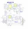
I'm not clear how your circuit is intended to function, but the way the relays are wired the current through L1 is the same direction whichever relay gets energised. Is that correct?
In the .png pic the in/out of U1 have been transposed.
In the Testing Circuit, ++ seems not to be recognised as a voltage source. The positive supply pin of one LT1017 has two labels (14, ++). LTspice doesn't always like that. If you want a node to have two labels, use a jumper (from the Misc folder).
question 1, no, they are supposed to be reversing relays.,
another oops, the in/out of U1 have been transposed, I'll blame that one on spice, & myself for not catching it.
The + supply was supposed to be V+, caught that one, way later after I posted it.
I was trying to make a 14 pin comparator, so 14 in on pin 3 and the ++ and the -- is the supply for the rest of the comparators.
it seems to be working, funny what you can do when don't you can't do it
Circuit is working like a charm, it makes turning the steering wheel half as hard(or twice as easy) as the store bought unit by having twice the current handling capability. I did some tuning and the sensor was slightly biased to one side,
so happy happy joy joy & thanks for looking,
Jeff
The real thing is working great, 25 miles last evening and NO hitches.
"it seems to be working, funny what you can do when don't you can't do it" refers to using 14 ++ on the same wire with out a jumper in Spice,
Question, in all sincerity, where did you gain your knowledge of LTSpice workings, especially the fine points like the jumper. Is it safe to assume you just read the entire manual or is there a school or seminar you went to or a lot of more extensive use.
Thank again for you support,
Jeff
Just by playing with it. When it doesn't do what I expect (which is quite often; I'm still a relative newcomer to simulation) I check the Help . I've also had a lot of assistance, in my early dabbles, from Eric Gibbs: he's the guru.
Since Jeff has a working circuit I'm not suggesting he do this, but for others starting a build you should use a separate ferrite bead and resistor for each FET. The bead slides onto the FET gate lead as far as it will go, then the lead is cut off so there is just enough left to solder on the resistor ( with an equally short lead). Ideally you end up with transistor body, bead, solder junction, resistor body with no gaps between them. Since the resistor has high peak current it is a good idea to use a composition type.
Thanks EinarA, I didn't know to bunch resistor and bead up on the FET gate, but I do believe it was the addition of the bead and resistor and getting the driver as close as possible that fixed my FET killing problem. My next problem was that the whole system kept dying which I believe was caused by my overloading of one of the LM317 that would heat up and shut down, taking the whole system down. The load resistor for the LM317 has been removed and the system is working great. The system is protected by a 20 aviation type circuit breaker which does pop if I over load the motor by continuing to turn once at the end of play or by turning to sharp while in 4 wheel drive with front and rear locker engaged, but haven't killed any more FETs for quite a while. I did add some hysteresis to the relay driver circuit, but I don't think I had too. It was while adding the hysteresis resistors that I noticed the hot LM317. When I rebuild the circuit and combine it with other circuits, I will follow your advice.
FYI, it was U18 or U20 depending on which drawing you look at, that was being overloaded by the 47.8 Ω resistor, now gone.
This site uses cookies to help personalise content, tailor your experience and to keep you logged in if you register.
By continuing to use this site, you are consenting to our use of cookies.


")