Continue to Site

Welcome to our site!

Electro Tech is an online community (with over 170,000 members) who enjoy talking about and building electronic circuits, projects and gadgets. To participate you need to register. Registration is free. Click here to register now.

  • Welcome to our site! Electro Tech is an online community (with over 170,000 members) who enjoy talking about and building electronic circuits, projects and gadgets. To participate you need to register. Registration is free. Click here to register now.

Still killing IRF3205 FETS

Status
Not open for further replies.
I did email IR about my problem, thought you all might like to read the reply,
Subject
irf3205
Discussion Thread
Response Via Email
06/25/2014 04:55 PM
Hello Jeff,

There should be current limiting resistors connected to the gate of the mosfet's always. 10-20 ohms. current from NE555 is 200mA. if a 10 ohm resistor is selected. I^2xR = .2x.2x10 = 0.4 W 10 ohm resistors can be used. Gate resistors are always important or the mosfet's can be damaged. They limit the current and also make sure there is no transient spike coupled at the gate.


Best Regards,

Kali
Applications Engineer
Technical Assistance Center
International Rectifier
THE POWER MANAGEMENT LEADER

Customer By Web Form (Jeff )06/25/2014 10:06 AM
I have 19 dead IFR3205 in my hand and I have probably thrown that many away, the markings are
IRF3205
I R P138
B9P0
Death was determined with a diode check using a Fluke multi meter and the Vgs usually read near 0 volts, as did the Vds ad Vgd, regardless of polarity
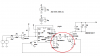
I've tried multiple gate drivers, IR2110, totems, and last try was the output of a ne555, but my IRF3205s keep dying, Last kill was, using the uploaded drawing, apply the PWM to a gear motor, 12v 185 watt, one shaft having a sensor similar to a Wheatstone bridge and the other shaft is power output. I held the output with some pliers a while turning the input shaft and watched the current from my power supply, with 2 IRF3205s in parallel, I should have over powered the supply and should not have been able to stop the gear motor, instead, at about 15 amps, one of the IRF3205s failed shorted, again!
This cause the gear motor to catch up and pass the input signal and then it reversed because it passed the input and it bounces back and forth until I can get free.
These are 110 amp FETs and shouldn't be dying at 15 amp,
One question I have is are these your product or did I get a knock off?
Can you suggest a design change suggestion or any help.
Thanks you,
Jeff


So, I'll be adding a resistor to the gate of this and all future designs, an omission that was pointed out earlier in this thread.
 
Well done IR for a helpful reply! Hope that your FETs will now survive, Jeff
 
Vgs=12 Isd=15 temp probe heat shrinked or shrunk to drain lead close to IRF3205 body, lead temp 65C and stable, surrounding metal stayed cool to touch.
Added 22Ω resistor between NE555 and IRF3205 gate,- and another one bites the dust. :banghead: :banghead: :banghead:!!
The dead store bought unit I have has a 33μh torroid inductor that I think is in series with the out put. I'm thinking of adding it to my circuit, when I find it again.
I wonder if my power supply is pulling down and causing problems, maybe I will try a battery tomorrow.
 
Sound like you are Getting Transient High Voltage SPIKES.
They may easily Exceed the 55 Volt rating of your Fets, causing them to fail.
 
Any theories as to where they are coming from? Last FET death happened while loading it with the stalled motor, .245Ω, at about 10 amps and as I was increasing the demand, I stopped abruptly and it failed, probably an inductive kick back, I think if failed to hook up the protective diode, STTH10R04, source to drain
 
Also try putting a 13-15v zener between gate and ground - this should rule out high voltage spikes killing the Mosfets that way.

What kind of PSU are you using to supply the circuit ? Is it a regulated one ? Car battery ? Running car system ?
 
I Doubt transients on the Gate are distroying the Mosfet.
I find its usually Drain to Source.
What is that "STTH10R04"?

More likely your power supply might Contribute to the Problem.

A Battery has a Much LOWER Impedance than any Power Supply, which Might prevent this problem.

Not Sure I have seen Exactially, your Total Circuit.
But about your Relays, They can also Create Switching spikes.
 
So wait, it worked when you had a constant 12V on the gate but died when you used the 555? Or was that always with the 555?
 
I Doubt transients on the Gate are distroying the Mosfet.
I find its usually Drain to Source.
What is that "STTH10R04"?

More likely your power supply might Contribute to the Problem.

A Battery has a Much LOWER Impedance than any Power Supply, which Might prevent this problem.

Not Sure I have seen Exactially, your Total Circuit.
But about your Relays, They can also Create Switching spikes.
STTH10R04 400v 10a ultra fast diode I suggest google it.
If you need a better explanation of the circuit, let me know, but it is a power steering assist for off road vehicle.
The setting in the circuit allow for timing the PWM and relays so that the relays energize before the 555 gets the trigger and loses the trigger before the relays drops out.
 

Attachments

  • POWER STEERING 2014-06-27 - Copy.png
    POWER STEERING 2014-06-27 - Copy.png
    92.5 KB · Views: 686
So wait, it worked when you had a constant 12V on the gate but died when you used the 555? Or was that always with the 555?
worked well with 12 v on gate (no switching) so all the losses were due to RDS(on) = 8.0mΩ X 15a X15a

Today, I think I got it figured out, maybe,
#1 the IRF3205 was getting so hot so fast and that it couldn't get rid of the heat with the silicone isolator, measuring temp on the drain lead, it would go over 100C in way less than a minute.
#2 the inductive kick back was very close to the voltage rating, My scope measure it at just over 50v p-p and my Fluke was saying 24 v. I tried a IRFp460LC, 500v, 20a, RDS(on) = .27Ω and it had an inductive kick back high enough to take out the 400 v 10a diode. My scope measured the p-p as over 400v and as I would increase the demand, it started making noises, so I didn't push it very hard.
#3 as I increased the demand, the voltage drop on my leads and the psu would cause the voltage at the gate to start dropping into the linear region and I could feel the loss of torque, or that's my guess at what was happening.
The power supply is a home grown design using a 12 v 20 amp battery substitute.https://www.electro-tech-online.com/threads/rebuilding-my-power-supply.139397/page-6#post-1177961
 
Last edited:
So now I'm wondering why my protection diode wasn't keeping the kick back voltage down. Do I have it in the wrong place.
This is a bad scope shot, as I would add more demand, the oscillation would disappear and square off at the oscillation ~24-50 v (red trace) (yellow trace is gate)
 

Attachments

  • 1.png
    1.png
    133.3 KB · Views: 463
Last edited:
Your Diode may be Ultra Fast, But it Breaks down at 400 Volts.
Your Mosfet is rated at 55 Volts.
So the Mosfet is probably trying to Clamp the Spikes.


Ideally your diode should be Ultra Fast at 50 Volts, so it Clamps the Spike Before exceeding the Max voltage of the Mosfet.

#1 the IRF3205 was getting so hot so fast and that it couldn't get rid of the heat with the silicone isolator, measuring temp on the drain lead, it would go over 100C in way less than a minute.
I Doubt that is the Problem, But I don't Like Silicon Insulators.
I Alway try to Insulate the Heatsinks.
 
Your Diode may be Ultra Fast, But it Breaks down at 400 Volts.
Your Mosfet is rated at 55 Volts.
So the Mosfet is probably trying to Clamp the Spikes.


Ideally your diode should be Ultra Fast at 50 Volts, so it Clamps the Spike Before exceeding the Max voltage of the Mosfet.
Eh ? It should clamp the reverse spikes at its reverse voltage. Probably ~1V to 2V

It is capable of spikes of up to 400v before being damaged.

You may be confusing the clamping diode with a zener diode.

The speed of the diode is also important as if your spike is a fast one, the diode won't clamp until a higher part of the spike voltage exposing the protected item to a higher voltage.
 
Yep, the diode's in wrong, needs to be cathode to +14 & anode to drain.
Some where I read or someone said that the body diode was sufficient for back EMF, I think from what I saw on my scope is if you have a 55 volt FET, you'll get a 50+ volt kick back voltage, If you use a 500 v FET, you'll get a 400+ kick back, high enough to kill a 400 volt diode that's in wrong, just the way I see it.
 

Attachments

  • POWER STEERING 2014-06-27 - changed.png
    POWER STEERING 2014-06-27 - changed.png
    96.3 KB · Views: 972
Interesting development, after putting the diodes in correctly, I could not hold the motor torque at much above 5 amps, before, I could hold it back at 10 amps.
made it through the day WITHOUT killing any FETs, :happy:, put the unit on my vehicle and I am getting it tuned in, if I can get it set up, it will be easier than the store bought unit.:woot:
 
Hmm, just read this thread.

I destroyed about 8 IRFP3206 (2 batches of 4 in parallel) last year due to a combination of kickback avalanche and ringing on the gate in a 500Hz hard switching circuit driving up to 700 Amp pulses @ 36V.
They would collapse in domino fashion after dozens of hours of service, making a solution difficult.

These Fets are ruggedized for avalanche (back emf) BUT they are derated based on temperature and that MUST be carefully observed based on the switched current.
The solution involved:
1) An 18V Zener plus blocking rectifier on the Gate to limit any spikes to 18.6V.
2) 5 ohm gate resistors PLUS a ferrite bead which makes a noticeable improvement in softening the switching edge overshoot spikes and prevented any Drain/gate capacitive junction coupled current spikes from harming the MOSFET driver chip. An MCP1407 FET driver was used driven by an optocoupler.
3) a 50SQ80 series schottky in series with a PEN 1uf Film cap (63V rated), rev biased across the output of the FET drive to short the kickback and reduce avalanche loading on the FETS.

The last item visibly reduced the peak kickback voltage to UNDER the kickback induced 75V AVALANCHE down to about 45V peak...eliminating the avalanche loading on the FETS.
 
Sounds good!
Thanks
 
Mosaic, Is this the set up you were talking about?

I have used feed back to CV of the 555 in the past and I worked well, If I use feed back as shown in the drawing, do you think it will work? or turn the FET into a heater. Spice show the feed back to CV creating a high frequency which should cause high switching losses.
Away from home,
Jeff
 

Attachments

  • Post.png
    Post.png
    21.9 KB · Views: 1,013
  • Post.asc
    5.4 KB · Views: 196
The schottky and 1uf film cap go from Drain to ground, effectively bypassing the FET avalanche.
Due to the high avalanche currents I had to deal with, the freewheel diodes would burn up as they tried to clamp at under a volt. I was pulse discharging (500Hz) a 15Kuf LOW ESR cap bank into an RLC load.
The 1 uf film cap ESR and heavy duty pulse 50SQ schottky formed a DC blocking path for back emf which permitted clamping at about 45V based on the kickback currents. This is below the avalanche voltage of the FETS I had. Avalanche happens at around 10% greater than VDS rating.
I tried to use a heavy duty TVS diode rated at around 40+ V but it popped after a few minutes.
https://www.newark.com/littelfuse/1-5ke43ca/tvs-diode-1-5kw-43v-do-201/dp/17H2660

Clamping backemf at a higher (but still safe) voltage reduces the pulse current load on the freewheel diodes.
The capacitor pulse bank absorbs the back emf.

The control voltage needs to be smoothed in order to modulate the pulse width properly.
You need a pi filter to produce a variable DC voltage for the CV from the PWM current in the sense resistor. Also you'll need a collector pull up resistor to provide a load for the transistor drive. You'll want the base drive to vary between 0 to .6V and you'll need to calc the base current for a base resistor as per the HFE of the transistor and the Ic as per the collector pullup resistor. You may need to bias the base with a voltage divider to get things to work properly. If u have a good spice transistor model you should be able to whip that up pretty quick.
 
Last edited:
Status
Not open for further replies.

New Articles From Microcontroller Tips

Back
Top