gramo
New Member
Code:
	Result = 0
	Total = 0
	X = 0

	Repeat

		  DelaymS 1

		  Result = ADIN 0
		  Result = Result * 2
		  Total = Total + Result

		  Inc X

	[B]Until X = 100[/B]

	Total = Total / 15

	Total = Total * 5 / 1023
Change the number of samples too 100 like I did above, you could even go higher, but it will slow down your program. This should help smooth the Speedo
Leave 7.2 in this part, dont round it
Code:
Temp_Float = KMHT
Temp_Float = Temp_Float * 4 * 7.2
KMH = Temp_Float / 1000
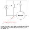
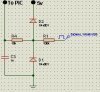
KMHT = KMHThe issue with the miss reading could be the impedance is too high for the ADC circuitry in the PIC. The datasheet specifies 2.5K Max impedance. This is to allow the internal capacitors on the PIC to charge and discharge properly, try use 2.2K resistors on the voltage divider.
Let me know if that helps
")