Continue to Site

Welcome to our site!

Electro Tech is an online community (with over 170,000 members) who enjoy talking about and building electronic circuits, projects and gadgets. To participate you need to register. Registration is free. Click here to register now.

  • Welcome to our site! Electro Tech is an online community (with over 170,000 members) who enjoy talking about and building electronic circuits, projects and gadgets. To participate you need to register. Registration is free. Click here to register now.

Sony Infared Code in C18

Status
Not open for further replies.
here is a schematic now:
ir_relay-png.29919
 

Attachments

  • IR_Relay.png
    IR_Relay.png
    11.5 KB · Views: 673
Hey guys im having a RELAY issue or at least i think it is a relay issue...

For some reason the light stays on even if its supposed to be off.

This is the relay im using:
relay-png.30343


This is my Ballast info:
ballast-png.30342


The relay is supposed to be 1A which should be fine since ballast calls .8amps aka 800mA...

is that too close? should i just use a higher relay? or do you think its the transistor switching it? ima use a multimeter now to test that.
 

Attachments

  • ballast.png
    ballast.png
    242.5 KB · Views: 607
  • relay.png
    relay.png
    241.6 KB · Views: 626
im using the below relay for now. Its 125v @ 1A. At least its holding well for now. Until i can order new relays.

relay2-png.30345
 

Attachments

  • relay2.png
    relay2.png
    133.2 KB · Views: 418
Last edited:
so a 3A+ relay should be perfect right? I need to order one so i want to make sure i get it right :D

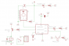
I don't know, but it stands more of a chance - you've probably seen light switches arc inside when you turn a flouescent light off? - that's due to the inductance of the choke.

Just like why you have to have a protection diode with a relay driver (I'm presuming you have that?), it's the back-EMF from the inductance.
 
hey Nigel i know you should be able to answer this...
Code:
The protocol uses bi-phase modulation (or so-called Manchester coding) of a 
36kHz IR carrier frequency. All bits are of equal length of 1.778ms in this protocol,
with half of the bit time filled with a burst of the 36kHz carrier and the other half being 
idle. A logical zero is represented by a burst in the first half of the bit time. 
A logical one is represented by a burst in the second half of the bit time. 
The pulse/pause ratio of the 36kHz carrier frequency is 1/3 or 1/4 which reduces
power consumption.

    * Carrier frequency of 36kHz
    * Constant bit time of 1.778ms (64 cycles of 36 kHz)
    * The recommended carrier duty-cycle is 1/4 or 1/3.
...When it says frequency of 36 kHz should i divide 1/36000... =0.000 027 777 777 8

which is essentially 0.00002777 Seconds aka 27.77uS (microseconds). So if i use 1/3
as the duty cycle im supposed do it like: 27.77 / 3 = 9.256uS is the 1/3 now 2/3 of it is 9.256 *2= 18.513uS.

So i should turn on the IR Led for 9.256uS then off for 18.513us .

Knowing this:
Code:
 All bits are of equal length of 1.778ms in this protocol, with half of the bit time filled with 
a burst of the 36kHz carrier and the other half being idle.

i should pulse at that rate for 1.778ms / 2 = 889uS. If thats the case i should divide 889uS / 27.77uS = ~32 which means i should send out:
Code:
32x loop:
9.256uS = pin high
18.513uS = pin low
32x loop
27.77uS = pin low

to produce a logic 0?

SB-Projects: IR remote control: Philips RC-5

I know this isnt sony but its IR and wanted to test my theory of thinking :D
 
Last edited:
3 amp would work fine When your light first comes on it will pull 1.5 amps till it lights the bulbs. there always a inrush of current with fluorescent light bulbs till they fire
 
I realize that this thread has been dormant for over a month but...

I was playing with Jason's code and discovered that no matter what button I pressed to be learned afterwards only the "1" button would activate the LED that I substituted for his relay on pin 3 (GPIO4). After reading through the code a couple of times I found his mistake. In this section of code:


Code:
MainApp:
    MainAdd = ReadEE(0x00);
    MainCmd = ReadEE(0x01);

    while(1){
        GetSIRC(&MyAdd,&MyCmd);

        if(MyAdd == 0x01)
            if(MyCmd == 0x00){
                if(IsSet == 0){
                    RelayPin = 1;
                    IsSet = 1;
                } else {
                    RelayPin = 0;
                    IsSet = 0;
                }
            }

        delay_ms(250);
        delay_ms(250);
  }


this:

Code:
 if(MyCmd == 0x00)


should be replaced with this:


Code:
if(MyCmd == MainCmd)

This post is not meant to degrade Jason or his work. He did a good job in commenting the code and in creating it to begin with. I was looking at it to integrate with other code for dimming lights and controlling AC motor speed. Now I just need to modify what he has done to allow multiple buttons to be learned and get that integration thing done.

Mike
 
heh thanks i forgot to edit that. As you can see from my usetube videos i do have it working and still use it for my lights :D

Multiple codes arent too hard. A LCD would help or some LEDs to show what code is being programmed.
 
Hi again AtomSoft :)

lovely work!!. Is it possible to somehow make the transmitter and receiver for your code on Proteus?

I wanted to use your code but add a few more buttons in the transmitter.

Please kindly help.
 
I have tried your code on 18F1320.

It works perfect on 8MHz clock. However when i change the clock to 4MHz, it doesnt quite work.

I thought it would be easy to convert it from 8 -> 4 MHz just by reducing all the delays to half but that also doesnt work. Can you please guide a little on how to use your code on other clock speeds?

Yes i am using external clock.
 
Thank you for replying Atom :)

I have been stuck with it for quite some time.
I have attached the complete folder i am working in. It contains the Simulation aswell

I am trying to send like several commands from the transmitter to the receiver using IR link to modulate and demodulate.

However only two commands are recognized.

Transmitter:
#include <p18cxxx.h>
#include <delays.h>

#pragma config WDT = OFF, LVP = OFF, OSC = HS, DEBUG = OFF

#define keypadPort PORTB // Keypad attached with PORT
#define keypad_DA PORTBbits.RB4 // Data Enable pin of Keypad Encoder

#define irPin LATBbits.LATB7

void main(void);
void ReadKeypad(void);
void SendSIRC(unsigned char Dev, unsigned char Cmd);
void PulseIt(unsigned char time);

ram unsigned int keypress_count = 0;
ram unsigned int keypad_loop_flag = 0;
ram unsigned char keyNum;

void main(void){
unsigned long i = 0;
ADCON1 = 0xFF;
TRISA = 0x00;
TRISB = 0b01111111;


while(1)
{
for(i = 0; i < 1000; i++)
{
SendSIRC(i,i);
Delay10KTCYx(100);
PORTA = i;
}
// ReadKeypad();
// PORTA = keyNum;
}
}

void SendSIRC(unsigned char Dev, unsigned char Cmd)
{
char x;
PulseIt(4); //Logic Start

for(x=0;x<7;x++){
if(Cmd & 0x01)
PulseIt(2); //Logic 1
else
PulseIt(1); //Logic 0
Cmd <<= 1;
}
for(x=0;x<5;x++){
if(Dev & 0x01)
PulseIt(2); //Logic 1
else
PulseIt(1); //Logic 0
Dev <<= 1;
}
Delay10KTCYx(90); //45mS Delay
}

void PulseIt(unsigned char time){
unsigned char x,y,z;

for(y = 0; y < time; y++)
{
for(x=0;x<24;x++) //600uS worth
{
irPin = 1;
Delay10TCY();
Nop();
Nop();
Nop(); //About 7uS
irPin = 0;
Nop();
Nop();
Nop();
Nop();
Nop();
Nop();
Nop();
Nop();
Delay10TCY();
Delay10TCY(); //About 18uS
}
}

for(x=0;x<24;x++) //600uS worth
{
irPin = 0;
Delay10TCY();
Nop();
Nop();
Nop(); //About 7uS
irPin = 0;
Nop();
Nop();
Nop();
Nop();
Nop();
Nop();
Nop();
Nop();
Delay10TCY();
Delay10TCY(); //About 18uS
}
}


void ReadKeypad()
{
if(keypad_DA != 1){keypad_loop_flag = 0;return;}
keyNum = keypadPort & 0x0F; // Stripping keypad related bits (Change to 0xF0 if keypad connected with MSB of PORT)
//keyNum >>= 4; // Shifting keypad bits to make them decimal equivalent (use in case keypad connected with MSB of PORT)
switch(keyNum)
{
case 0:
SendSIRC(1,0);
break;
case 1:
SendSIRC(2,0);
break;
case 2:
SendSIRC(3,0);
break;
case 3:
SendSIRC(1,4);
break;
case 4:
SendSIRC(1,5);
break;
case 5:
SendSIRC(1,6);
break;
case 6:
SendSIRC(1,7);
break;
case 7:
SendSIRC(1,8);
break;
case 8:
SendSIRC(1,9);
break;
case 9:
SendSIRC(1,10);
break;
case 10:
SendSIRC(1,11);
break;
case 11:
SendSIRC(1,12);
break;
case 12:
SendSIRC(1,13);
break;
case 13:
SendSIRC(1,14);
break;
case 14:
SendSIRC(1,15);
break;
case 15:
SendSIRC(1,16);
break;
default:
break;
}
Delay10KTCYx(1);
}

void lock_key(void)
{
while(keypad_DA == 1);
}

Receiver:
#include <p18cxxx.h>
#include <delays.h>
#include <string.h>

#pragma config WDT = OFF, LVP = OFF, OSC = HS, DEBUG = OFF

unsigned char lTime;

unsigned char MyAdd;
unsigned char MyCmd;

#define irPin PORTBbits.RB0

#define Led_6 LATBbits.LATB1
#define Led_5 LATBbits.LATB2
#define Led_4 LATBbits.LATB3
#define Led_3 LATBbits.LATB4
#define Led_2 LATBbits.LATB5
#define Led_1 LATBbits.LATB6
#define Led_0 LATBbits.LATB7


void main(void);
void GetSIRC(unsigned char *address, unsigned char *command);

void main(void){

TRISB = 0x01;
TRISA = 0x00;
ADCON1 = 0xFF;
PORTB = 0;
PORTA = 0;

while(1){
GetSIRC(&MyAdd,&MyCmd);
Led_0 = 0;
Led_1 = 0;
Led_2 = 0;
Led_3 = 0;
Led_4 = 0;
Led_5 = 0;
Led_6 = 0;
PORTA = MyCmd;
switch(MyCmd){
case 0:
Led_0 = 1;
break;
case 1:
Led_1 = 1;
break;
case 2:
Led_2 = 1;
break;
case 3:
Led_3 = 1;
break;
case 4:
Led_4 = 1;
break;
case 5:
Led_5 = 1;
break;
case 6:
Led_6 = 1;
break;
}
}
}

void GetSIRC(unsigned char *address, unsigned char *command){
unsigned char ir_add;
unsigned char ir_cmd;
char x;

StartLook:
ir_add = ir_cmd = 0;

while(irPin); //wait for it to be low
lTime = 0; //reset the counter

while(irPin == 0){ //while the pin is low which is our pulse count
lTime++; //increment every 200uS until pin is high
Delay100TCYx(4); //200uS delay
}

if(lTime <= 10) //Start too short
goto StartLook; //Restart
if(lTime >= 14) //Start too long
goto StartLook; //Restart

lTime = 0;
for(x=0;x<7;x++){ //repeat 7 times for command
ir_cmd >>= 1; //if it was skipped or is done ORing then shift over the 1

while(irPin); //wait for it to be low
lTime = 0; //reset the counter

while(irPin == 0){ //while the pin is low which is our pulse count
lTime++; //increment every 200uS until pin is high
Delay100TCYx(4); //200uS delay
}

if(lTime >= 6) //If its high then OR a 1 in else skip
ir_cmd |= 0x40; //if its less than 6 its a 0 so dont OR it

}
for(x=0;x<5;x++){ //repeat 5 times for address/device
ir_add >>= 1; //if it was skipped or is done ORing then shift over the 1

while(irPin); //wait for it to be low
lTime = 0; //reset the counter

while(irPin == 0){ //while the pin is low which is our pulse count
lTime++; //increment every 200uS until pin is high
Delay100TCYx(4); //200uS delay
}

if(lTime >= 6) //If its high then OR a 1 in else skip
ir_add |= 0x10; //if its less than 6 its a 0 so dont OR it
}

*address = ir_add;
*command = ir_cmd;
}
 

Attachments

  • Project_IR.zip
    481.1 KB · Views: 135
Last edited:
No i am not trying to learn commands. Just trying to make the transmitter for more channels. Like 16 channel for example.

the receiver should be able to distinguish among each channel (like in normal IR TV control)
 
Status
Not open for further replies.

Latest threads

Back
Top