Continue to Site

Welcome to our site!

Electro Tech is an online community (with over 170,000 members) who enjoy talking about and building electronic circuits, projects and gadgets. To participate you need to register. Registration is free. Click here to register now.

  • Welcome to our site! Electro Tech is an online community (with over 170,000 members) who enjoy talking about and building electronic circuits, projects and gadgets. To participate you need to register. Registration is free. Click here to register now.

Some More Simple FM Transmitters

Status
Not open for further replies.
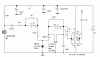
There is a similar FM transmitter that uses a 10.7Mhz crystal filter from the IF of an FM radio as its oscillator. Then Cmos inverters clip it into aquare-waves and its output at the 9th harmonic is at 96.3MHz.

I don't think an ordinary CD4069 inverter works at a frequency as high as 10.7MHz. Maybe a 74HC04 is needed with a 5V supply.
 

Attachments

  • Digital FM transmitter.gif
    Digital FM transmitter.gif
    6 KB · Views: 2,821
I fear there is no filter that would select 9th harmonic, as such, we cant, say it would not interfere at many other frequencies.-- in the FM band
it will be seen as 9th harmonic -may be. the actualtransmitted energu may be perhaps 10.& only.
as 4069 is working with a 9V supply, it might cover upto 10 or 12 MHz
 
mvs sarma said:
I fear there is no filter that would select 9th harmonic, as such, we cant, say it would not interfere at many other frequencies.-- in the FM band
It has a square-wave output so its even harmonics are low.
It has very low output power so it won't cause much interference.
Its higher harmonics are low level and might be on a TV channel's frequency.
Its 7th harmonic at 74.9MHz is not in the FM band but might be a TV channel in some countries.
 
Are those transmitters the same as the ones located in rc stuff like cars and stuff? Could anyone tell me the requirments to make one of these that can control motors for at least 20 ft?
 
GreenAce92 said:
Are those transmitters the same as the ones located in rc stuff like cars and stuff? Could anyone tell me the requirments to make one of these that can control motors for at least 20 ft?
These are wideband FM transmitters for the FM broadcast band.

Cheap RC transmitters are just a single transistor that has AM modulation and a single transistor "radio receiver" that is a super-regen receiver.

Good RC transmitters and receivers use a quartz crystal for frequency accuracy and many transistors and ICs for digital FM.
 
What about the 72mhz transmitters? I just need to know how to make a simple transmitter + receiver which i can then plant into an rc vehicle. This is jsut to learn and its not for long. I am buying a real transmitter system but i just want to learn how it works and how to build one and modify to do what i want to do.

Any help would be appreciated.
Thanks.
 
Audioguru,
Do you have a coilless 27 Hhz AM transmitter schematic, I mean with X-tal. My experience, I have that schematic that was very simple but I lost it. My current project is building a 27 Hmz walkie talkie. Can you help me?
Thank's.

harries
 
Every transmitter that I have ever seen except one, uses coils and capacitors in a tuned circuit to reduce harmonics that cause interference at other frequencies. The one that doesn't use a coil operates from the 9th harmonic of a 10.7MHz ceramic filter. It is very low power so its other harmonics don't cause too much interference.
Transmitters with a crystal also use a tuned circuit with a coil.

I just looked in Google for Walkie Talkie Circuits and found a few. It even had a link to a thread here about walkie talkie circuits.
 
Audioguru,
I spent alo of times in Google for that, but not found yet. Ok now I understand that. Actually, I have a walkie talkie schematic attached. Receiver and oscilator coils are from 0,5mm on oscilator coil 8mm with 9 turns. RFC is from 0,5mm on 0.5cm free air coil with 33 turns.


my problems are :
1. I don't have a 27Mhz signal generator to tune that circuit. Can you help me?
2. The sound modulation is very low. How to solve this problem?
3. How to increase the distance?
Thank's for help.
 

Attachments

  • walkietalkie003.jpg
    walkietalkie003.jpg
    268 KB · Views: 1,361
Your walkie talkie doesn't work well because it is cheap.
Its parts cost about $2.00. It cannot be tuned.

The schematic has an error: The collector of Q1 is supposed to connect to something with negative DC on it.
 
Dear Audiguru,

I would like to build your FM Transmitter, but I have the dificulties to find transistor 2N3904 in my town. I would like to substitute Q1 with C829 for preamp mic, Q2 with C930 and Q3 with C930 or C1970. Is it possible to do?
Thank's
 
Try the 2N2222A, those transistors you suggested sound really old.
 
The 2N3904 transistor is extremely common. Maybe it is not available in the Orient. A BC547 is almost the same but its pins are reversed.

The old Yapanese transistors are completely different.
The max allowed collector current for the 2SC930 is only 30mA.
The 2SC1970 power transistor has a huge range of hFE from 10 to 180 and its capacitance is too high.
 
Older thread -newer question

How long is the red wire antenna on your transmitter audioguru?f
From the point of attachment to the board.

Have you experimented at all with a very fine wire which will tend to sharpen the bandwith
 
tytower said:
How long is the red wire antenna on your transmitter audioguru?f
From the point of attachment to the board.
I tried it with a quarter-wave length. 80cm.

Have you experimented at all with a very fine wire which will tend to sharpen the bandwith
The tuned circuits and the amplitude of the modulation determine the bandwidth, not the wire gauge of the antenna.
 
audioguru said:
The tuned circuits and the amplitude of the modulation determine the bandwidth, not the wire gauge of the antenna.

I take it you are not a radio ham?
Wire cross -section of the antenna is quite a factor at HF
 
Status
Not open for further replies.

New Articles From Microcontroller Tips

Back
Top