Continue to Site

Welcome to our site!

Electro Tech is an online community (with over 170,000 members) who enjoy talking about and building electronic circuits, projects and gadgets. To participate you need to register. Registration is free. Click here to register now.

  • Welcome to our site! Electro Tech is an online community (with over 170,000 members) who enjoy talking about and building electronic circuits, projects and gadgets. To participate you need to register. Registration is free. Click here to register now.

Solid State Tesla Coil Burning Mosfets

Status
Not open for further replies.
I just read up on some of the specs of the DS202 and my suspicion was confirmed -- It only has a bandwidth of 2MHz. This means you will not see any of the artifacts I'm looking for in the bridge switching waveforms. As I said before, the DS202 is NOT SUFFICIENT for this sort of project. Even a 20MHz scope will not show you everything you need to see. You really MUST have a bandwidth of 100MHz or higher.

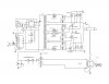
What I am looking for, specifically, are the large spikes every time the bridge switches. These spikes are due to the MOSFETs trying to switch the direction of current in the primary coil when there is still current flowing through it. The goal is to switch the direction of current when the current is crossing zero. This is called Zero Current Switching (or ZCS). This prevents the large inductive voltage spikes which can damage your transistors. This is the purpose of phase lead. Phase lead allows you to adjust when the H-bridge switches. You can adjust it to switch exactly when the current is crossing zero, thus protecting your transistors. Otherwise, as I mentioned before, your MOSFETs end up switching a little bit too late (due to the hundreds of nanoseconds or several microseconds they take to turn on after they first receive the signal on the gate) which means they try switching the direction of the current in the primary when there is already current flowing through it. Again, this generates the voltage spikes that can cause shoot-through (an arc within the MOSFET that shorts the drain to the source).
 
Which can also a be an artifact of the breadboard. I don't understand why that can't be understood in this?:confused: If you think all of your "work" will transfer when going to a true PCB after doing this on a breadboard, get ready to do it all over again there.:arghh: It doesn't need to be "pretty" now, just off of a breadboard.
 
Which can also a be an artifact of the breadboard. I don't understand why that can't be understood in this?:confused: If you think all of your "work" will transfer when going to a true PCB after doing this on a breadboard, get ready to do it all over again there.:arghh: It doesn't need to be "pretty" now, just off of a breadboard.
Exactly right. Anything you (the OP) does now is ultimately meaningless because it will behave in a completely different manner once you do eventually transfer it to a PCB. Designing and building a DRSSTC is not a simple task, and soldering/desoldering IGBTs is probably one of the easiest parts of the process. Better get used to it.
 
Even the original form of breadboarding, using a piece of wood, small nails or tacks, and point to point wiring would be better than a plastic modern breadboard. But it's not my time and components being wasted, so do as you want.
 
Sry I forgot to post the voltages read I also just said screw the probes for now and just use matched resistors as probes so I get equal inputs. I will post new scope views tomorrow with values. My apologies.

Okay well I looked at my gate signals, With 56 ohms, I think that's to high, I get a good dead time but my upper portion of the front of the square is quite rounded. This in my mind would slow the switch ON, there for dissipating a lot of power as heat. Not there yet but I saw this and have lowered that resistance to 10hms, I still get a view-able dead time, around 1 us.

I also have noticed why I earlier thought my zeners where not clamping. Not sure if I mentioned this but I saw my gate voltage was at 12v when using 2 5.1v zeners. I now noticed I was being quite stupid and was looking at VPP so I was looking at the negative side as well. I was thinking in series it was doubling the reverse voltage of the zener LOL... So I am getting 19.8-20.4v at the gate VPP. my scope being so small I can barely read the settings lol.

So now I am getting 10v and clamped to max 15v at the gate, I also am swinging -10V wile off. So this takes the miller effect as well as gate voltage spikes out of the question.

I figure I'm okay with the 24ns MUR460 diodes to protect against freewheeling current. Do I need Schottkys at the drain to insure body diode does not forward bias?

Shoot through should be tackled with the 1us deadtime(I will post gate waveform with new 10OHM resistors) this also helps the fets switch on faster.

I dont think I am any where near prolonged currents since I am not getting heat.

Is there something I can add here to prevent Ringing of the fets?

So I think this leaves two outcomes, One the bread board is causing massive problems, Or two the driver circuit being open to air, same height, and within 4 feet of tesla is introducing RF interference making fets wrongly turn on. So I will post these scope views tomorrow. I'll then Cage my driver circuit as well as make a temp PCB board for my H-bridge before my next test. So lets hope this is it!!!

Thanks for the help guys, I do very much appreciate it.
 
Also I cannot for the life of me get that guys feedback transformer to work. its simple 50turns with secondary ground ran through the toroid ring. I tried flipping connections and way the wire went thinking phase was off. but I cannot get a signal when on transformer leg is grounded. If I leave one end open and other as feedback to inverters it works but isnt that just a wound antenna then? I tried a number of different cores and just cant get it. its like when I ground one of the two pins I just am pulling the inverter to ground so then not pulsing at all ...WTF??? any thoughts on that?
 
My apologies I must have been posting wile multiple people were. I have just now saw the first post where you were talking about phase lead. What you're saying makes complete sense to me although wouldn't that be handled by the fact I have-10 volts on the gate when it is not switching there for needing positive 11 volts to cause any type of switching? Also I do have a 151 ceramic capacitor bleeding any high frequencies from my antenna input to ground.. I do know my scope does not go above that bandwidth, that is why I usually look up the precautions I need to take to handle them. Am I way off here is there something I'm completely missing to get rid of that noise. And I'm sorry about not posting scope pictures today I got off late and was working on my temporary PCB board which is now complete. I'll post pic tomorrow once it is soldered
 
This is my temp board. I hope I did the traces thick enough. I got 90mils wide on my calculations. So I did 180mils. Supply lines are 240mil.
 

Attachments

  • received_10208479140848408.jpeg
    received_10208479140848408.jpeg
    151.8 KB · Views: 161
Quite honestly, until you show that you've done your research and demonstrate that you have a more complete understanding of how DRSSTCs work, I'm hesitant to help you any further. I am glad you made a PCB, but that is only one of our suggestions that you followed. You seem to be ignoring everything else. And someone asking questions and then ignoring the answers does not reflect well on them, and often turns away other people who would otherwise want to provide assistance.
 
Okay well I'm even more confused now. Am I not seeing some posts on my end? I re-read this whole thread. So far the only thing suggested was a breadboard is junk and I don't have a high bandwidth scope. As well u mentioned IGBT's are used for a reason as well as my pulse width is two wide. I appreciate that but right now im not getting heat, shouldnt that take those out of the question, especially since I had 40x the run time no issues at the beginning, before I blew the dimmer. I mentioned as soon as I can run this, see I am getting hot with runtimes increasing, I will absolutely switch to IGBT's and go to an Arduino board with proper pulsing. Then was the freewheeling diodes I mentioned I have external mur460's there.

So I do apologize I can't get u a waveform based on Equipment your used to but I've seen these made with less and I'm not going g to spend $500 on a 20$ project. I had every part new inboxes other than the IGBT's. That's what cost me 20$. I do understand I can't see things that may need to be, but like I said before can't you take the necessary steps to insure this won't happen?

If I'm missing something please don't just leave me hanging I am taking everything into consideration. The only things I haven't done are swap out for IGBT's, shorten pulse width and buy a new scope.

I already mentioned the scope, but is my logic that flawed on the IGBT's and pulse width? Shouldn't I see heat? Especially with the 5+ 5min runtimes I had in the start with no heat and no zeners? I don't think it will hurt to throw the Arduino on there, but this has and can be done with fets. And I have a ton. Shouldn't that be a good enough reason to just use them for testing?

Im am also confused o. You DRSSTC statement. I have done about 6months of research, maybe what I read was all fake but if memory from research serves correctly. Im not even making a DRSSTC that would require a resonant tank capacitor in series with the primary coil.
 
Let's break this down. I've been over this already, but since you apparently aren't seeing it....

I mentioned as soon as I can run this, see I am getting hot with runtimes increasing, I will absolutely switch to IGBT's and go to an Arduino board with proper pulsing. Then was the freewheeling diodes I mentioned I have external mur460's there.
As I already said, you may not even notice the heating of the MOSFETs from the outside. The damage usually begins on the inside and works its way out. Also, because they act more as resistors in this sort of project, MOSFETs are extremely lossy and will not operate efficiently. They will waste power that would otherwise be transferred to your secondary coil, and will not contribute to the resulting output. Heating is definitely an issue (internal especially) but it is not the only issue. For some standard SSTCs MOSFETs will be sufficient because of the low primary currents, but DRs require much higher currents, and thus require IGBTs.

So I do apologize I can't get u a waveform based on Equipment your used to but I've seen these made with less and I'm not going g to spend $500 on a 20$ project. I had every part new inboxes other than the IGBT's. That's what cost me 20$. I do understand I can't see things that may need to be, but like I said before can't you take the necessary steps to insure this won't happen?
You should never put a budget on a DRSSTC. Trust me on this one, I learned the hard way. I'm afraid to ask where you managed to find the parts for $20. What are you using for a capacitor bank? What are you using for heat sinks? What are you using for the primary coil? What are you using for the secondary coil? You have failed to provide even a photo of your setup, much less an in-depth description of the parts and the build process so far.

If you want to be able to troubleshoot your coil, you cannot do it with the equipment you have. Period. Anyone who wants to build a DRSSTC needs to learn and accept this as an inevitability. The other option is to go the trial-and-error route and hope to stumble upon a working solution, but a) you'll go through a lot of damaged components this way (probably more than the cost of a secondhand scope from ebay), and b) you'll never know if you are actually running the coil efficiently or if you can improve it. My first oscilloscope cost me $70 and I have gotten several since for even less. If you have any interest in electronics, and continuing in the field, you should really invest in a digital scope. Even a cheap $300 Rigol would be well worth the money (it'll pay you back over time because it'll help you troubleshoot and avoid damaging more parts).

If I'm missing something please don't just leave me hanging I am taking everything into consideration. The only things I haven't done are swap out for IGBT's, shorten pulse width and buy a new scope.
All of which are very important and should be done ASAP.

I already mentioned the scope, but is my logic that flawed on the IGBT's and pulse width? Shouldn't I see heat? Especially with the 5+ 5min runtimes I had in the start with no heat and no zeners? I don't think it will hurt to throw the Arduino on there, but this has and can be done with fets. And I have a ton. Shouldn't that be a good enough reason to just use them for testing?
Using the MOSFETs instead of IGBTs is as bad as using a breadboard instead of a PCB. MOSFETs behave in a very different manner than IGBTs do, so testing with them is useless because the coil will not work the same when you swap them out. As for DRSSTCs being done with MOSFETs, anyone who has actually built a DR will tell you that they are a poor choice and will not work well, as I am now.

Im am also confused o. You DRSSTC statement. I have done about 6months of research, maybe what I read was all fake but if memory from research serves correctly. Im not even making a DRSSTC that would require a resonant tank capacitor in series with the primary coil.
The schematic you show in your very first post, for your H-bridge and Guangyan's full schematic, both are for DRSSTCs. In your H-bridge schematic C1 is the primary tank capacitor.

Not being able to tell the difference is another reason why I'm not confident in your understanding. I researched for several years and built several coils of different types before I started working on my DR.
 
I apologize I didn't post my whole setup

SECONDARY
  1. 3.5" OD ABS
  2. 1210 turns
  3. 36 gauge ( I know that's a bit small, it what I had, if it fries I'll make a 34 gauge)
  4. 3 coats of clear acrylic
  5. 54.487863mH 4.346pf Calculated
TOP LOAD
  1. Toroid
  2. 3" ducting
  3. 4" cooking Pans for center (x2)
  4. 11.122pf Calculated
Secondary with topload resonant frequency: 174.049KHz Calculated (173.3KHz read when self tuned)

PRIMARY (Helical)
  1. 4"
  2. 14 AWG
  3. 6 turns
  4. 0.375 spacing
  5. 28v 1.5amp power supply was best tuned to 2.75 turns with 4.7uf Cap
  6. It will stay lit up to 4 turns, 4+ does not light up
PRIMARY (Flat Spiral) made this due to secondary arcing when testing on dimmer
  1. Center 3.85"
  2. 3 turns
  3. coax cable
  4. 0.5" spacing
  5. best tuned at 2.5-3 turns
This is videos of it working on 42watts Helical primary:
This was modulating with music through a little lm348 pre-amp I made then thrown through an inverter.


So I do apologize I can't get u a waveform based on Equipment your used to but I've seen these made with less and I'm not going g to spend $500 on a 20$ project. I had every part new inboxes other than the IGBT's.
I got My IGBT's for about $5 each, Then the other parts are new, just leftover from other projects...


As for DRSSTCs being done with MOSFETs, anyone who has actually built a DR will tell you that they are a poor choice and will not work well, as I am now.
Okay well back to my original point, I have a ton of fets, Cant I get to a point of knowing it works before frying something I'm limited In. You also said for DRSSTC(I thought this was a SSTC since the guy making is called it one https://www.loneoceans.com/labs/sstc2/ He mentions the cap placed in series with his primary was a DC blocking cap nothing about a tank cap or adding power. As well this guy says a couple times that the DR difference is a cap is placed in parallel with the primary not in series so this was my confusion. I read on a different page he said series. I guess typo?) So If there so horrible for DRSSTC can I remove the 4.7uf cap to make it a SSTC and test with the fets?

I'm not trying to be a pain here but I know this can be ran on mosfets especially since it already did for 5 mins each, 5 times. Its something I have a lot of. Id like to do this with what I have. You said ur self don't work well. Not don't work. If you are absolutely 100% sure that's my issue then sure ill through my IGBTs in it. About internally heating up and popping, wouldn't enough heat to internally blow them slightly warm them? cuz there ICE cold. Its not that I'm not listening, its that it worked once like this. I have a problem, I'd like to go down all other roads first. That's why I'm doing the PCB board now and changing my ON time first. I would like to go through every suggestion you guys can give other than burning my only igbts I have right away. To be honest if this did not run for a total of 25mins at first on these fets at 60% power on the dimmer and not even get past warm, I would have already swapped to IGBT's. I'll try any suggestions, I just want to with fets, once all other culprits are brought off the table and it still wont work ill totally make the switch. Id rather blow 12 more $8 fets that I care less about then popping the only 4 I have for when this is working. So Im sorry can we just ignore the fets for now... Please

The breadboard to me sounds most likely, it ran for 25 mins total at 60% or less power, Once I cranked it with the 120w halogen I went way beyond the rating of that dimmer.(this was also theoretically on a somewhat half bridge(3 fets) since one of my low side fets output was not connected) That failure could very well have toasted that breadboard to the point of still working on low power but once power is high enough it maybe internally shorts. just a thought.......

Now I will add the arduino and try the pulse width you stated as well as try the PCB, is there any other suggestions you can make prior to going to IGBT's. Maybe something to help the fets, loose the 4.7uf tank cap for now? The cap is a 630v Polypropylene, Blue cap in videos. Possibly add more filtering on the antenna end? Any thing really, just to rule out on my next test.. Also did you see my post about the feedback transformer? any thoughts on why that wont work grounded?

Here are some pics, I will be working on the circuit itself tomorrow so I will add some updated scope photos.
 

Attachments

  • orca-image-1496033565338.jpg_1496033567142.jpeg
    orca-image-1496033565338.jpg_1496033567142.jpeg
    319.1 KB · Views: 123
  • orca-image-1496033639769.jpg_1496033640774.jpeg
    orca-image-1496033639769.jpg_1496033640774.jpeg
    363.9 KB · Views: 99
  • orca-image-1496033657538.jpg_1496033658414.jpeg
    orca-image-1496033657538.jpg_1496033658414.jpeg
    368.9 KB · Views: 117
Last edited:
Thank you for finally providing descriptions and images of your setup. A few things I noticed and a few answers:

1) You are running this in CW ("Continuous Wave") mode, which means no interrupter. That is an excellent way to destroy transistors (whether MOSFETs or IGBTs).
2) I did not look closely enough at the series capacitor value. 4.7uF is indeed for DC-blocking, and not for resonance (this is a bit embarrassing that I did not look closely enough at the value, so my apologies there).
3) Being a basic SSTC rather than DRSSTC, the currents will be lower so you may be able to get away with FETs after all, provided they are fast-switching and are rated for a high-enough voltage/current.
4) In a DRSSTC the resonant capacitor is connected in series with the primary, because the H-bridge needs to be able to switch the direction of current through both of them. Electrically you can have an LC resonant circuit with the cap in series or in parallel, but in an H-bridge (or half-bridge) they must be in series.

Which post has the question about the feedback transformer? Have you probed the waveform yet?
 
Also I cannot for the life of me get that guys feedback transformer to work. Its a simple 50turns with secondary ground ran through the toroid ring. I tried flipping connections and the way the wire went through thinking phase was off. but I cannot get a signal when one transformer leg is grounded. If I leave one end open and other as feedback to inverter it works but isnt that just a wound antenna then? I tried a number of different cores and just cant get it. its like when I ground one of the two pins I just am pulling the inverter to ground so then not pulsing at all ...WTF??? any thoughts on that?
Yes, when scoped, if one pin is grounded I get no reading on the other. If one is floating I get a decently clean wave on the other, isnt that a wound antenna tho?

1) You are running this in CW ("Continuous Wave") mode, which means no interrupter. That is an excellent way to destroy transistors (whether MOSFETs or IGBTs).
This was only in the videos, this was NC when trying mains, the music I thought acts as the interupter. If I do this down the road, do I need to have a modulating input as well as the music? Wont that make a constant(Buzz) frequency behind the music? or maybe have it transfer from music to modulation, so when the music isnt playing it swaps to the arduino, so it isnt in CW mode?

Right now I have the multi-vibrator @ 350hz 50% duty. I will switch to the arduino and shorten my on time as you stated. When running in this video I could run for 20mins straight and mosfets barley got warm, on 42watts with no modulation or music I could probably run it for an hour without heatsinks.(lol not saying do this I'm just stating it ran very cool, it did not seem like I had any crossover switching causing fets to heat up at all)

2) I did not look closely enough at the series capacitor value. 4.7uF is indeed for DC-blocking, and not for resonance (this is a bit embarrassing that I did not look closely enough at the value, so my apologies there).
Could you explain this to me? So is it the value that changes it to a DR?

3) Being a basic SSTC rather than DRSSTC, the currents will be lower so you may be able to get away with FETs after all, provided they are fast-switching and are rated for a high-enough voltage/current.
They are IXTQ50N25, 250v, 50a, 400W, switching times 14-24ns
https://www.mouser.com/ds/2/205/DS99346B(IXTA-TH-TP-TQ50N25T)-8804.pdf
 
Yes, when scoped, if one pin is grounded I get no reading on the other. If one is floating I get a decently clean wave on the other, isnt that a wound antenna tho?
Yes, if you leave one end floating then it becomes a basic antenna and not a current transformer. I am curious how you built your transformer. What are you using for a core? If I had to guess I would say you're using the wrong core material. Powdered iron toroid cores, for example, are extremely common and used in all sorts of applications (power supplies, especially) but are TERRIBLE at high frequencies. They are most often used for chokes, rather than transformers. For a CT you really need something with an extremely high permeability (>10,000). The cores I use can be found on Digikey (https://www.digikey.com/products/en?keywords=495-3868-ND). I would expect this is the most likely reason for failure.

This was only in the videos, this was NC when trying mains, the music I thought acts as the interupter. If I do this down the road, do I need to have a modulating input as well as the music? Wont that make a constant(Buzz) frequency behind the music? or maybe have it transfer from music to modulation, so when the music isnt playing it swaps to the arduino, so it isnt in CW mode?
Just because you're playing music through it does not mean it's acting as an interrupter. That depends completely on your driver circuitry, but it looks CW to me. Usually when someone wants to play music through a non-CW coil, they need to modulate the interrupter to play each note one-by-one. Your'e just overlaying the music over the CW frequency, ~170kHz, which humans can't hear.

Right now I have the multi-vibrator @ 350hz 50% duty. I will switch to the arduino and shorten my on time as you stated. When running in this video I could run for 20mins straight and mosfets barley got warm, on 42watts with no modulation or music I could probably run it for an hour without heatsinks.(lol not saying do this I'm just stating it ran very cool, it did not seem like I had any crossover switching causing fets to heat up at all)
Once again, SSTCs will be different from DRSSTCs in the sense that the MOSFETs will not see as much current, so they will not heat up nearly as much as IGBTs in a DRSSTC would. The lower duty cycle suggestion was more for DRSSTCs, which have much higher power transfer from the primary to the secondary, thus causing the primary to draw much more current. SSTCs do not have that second resonant circuit, though, so they draw much less current (and for that reason have a less impressive output).

Could you explain this to me? So is it the value that changes it to a DR?
Sure. In a dual resonant solid state Tesla coil the series capacitor is designed to resonate with the primary coil at the same frequency at which the secondary coil and topload resonate. This creates two tuned circuits which allows much more efficient energy transfer from the primary circuit to the secondary circuit.

I would expect your primary coil to be in the low uH range (let's just say 10uH for the sake of argument). If you have a 4.7uF capacitor connected to a 10uH inductor, your resonant frequency is 1/(2*pi*sqrt(L*C)), or 23.2kHz. This is far less than the frequency of the secondary circuit, so they are not two tuned circuits. Instead, this 4.7uF capacitor simply prevents your supply from being shorted out if the antenna "loses signal" or if one set of IGBTs latch up for any other reason, causing the supply to be connected directly across the primary coil. That is why it is referred to as a DC-blocking capacitor - it blocks any DC that might be applied to the primary coil. If you wanted to build a DRSSTC, you would size this capacitor in such a way as to match the 170kHz of your secondary coil. Let's just say that your secondary circuit resonates at 170kHz and your primary coil is 10uH, you would select your capacitor bank to be approximately 87.6nF (calculated by rearranging the formula above to solve for capacitance with respect to frequency and inductance).

Transitioning to a DRSSTC versus a SSTC would require other changes as well, though, so just stick with the SSTC for now.
 
Transitioning to a DRSSTC versus a SSTC would require other changes as well, though, so just stick with the SSTC for now.
Most definitely!! lol cuz ur right about a DRSSTC and my research. I have poked around in that area although I was reading how complex they are. So I was trying to stay away....LOL.... I tried to read all I could find about SSTC's. But awesome that makes complete since to me thanks for that.

Just because you're playing music through it does not mean it's acting as an interrupter.
I havent explained my driver setup fully but I thought I was modulating with music. I am simply amplifying a headphone output to 12V then using a inverter to clip every note, Therefor if I have a 1khz audio tone it is now a 12v square pulse repeating at 1khz, So I though I was converting my audio to pulse repetition frequency modulation. I thought it is modulating since I am not overlaying this on my resonance I am enabling and disabling my gate driver. If you look in the ACDC video the scope waveform is the square audio wave going to the enable pins. Back to a 1khz tone, I thought Im pulsing my 170khz resonate freq at 1khz. At least thats what I thought. I read if you modulate at 200hz you get a 200hz tone, so me turning my driver on and off at the frequency the music is at I thought would be the same. Its the same input I use to actually modulate with my miltivib. Am I way off here? If I am modulating maybe u got thrown off cuz I had the phase of Music input always high. so the arc was constant with no music. That was also just for testing I know thats suppose to be low so it only lights up when a musical tone is playing, therefor being off when muted. So I was practically turning it OFF at the music freq not ON in those videos.

Once again, SSTCs will be different from DRSSTCs in the sense that the MOSFETs will not see as much current, so they will not heat up nearly as much as IGBTs in a DRSSTC would. The lower duty cycle suggestion was more for DRSSTCs, which have much higher power transfer from the primary to the secondary, thus causing the primary to draw much more current. SSTCs do not have that second resonant circuit, though, so they draw much less current (and for that reason have a less impressive output).
So in your SSTC opinion would I be okay to test at 50% duty since its a lot less current then a DR? and possibly watch heat and change accordingly. Or is 50% on time on a SSTC way to high also?

On the core of the feedback transformer, I tried 4 different ones Im using toroids. I guess they all may not be ferrite. Ill poke around in my crap for some others. I usually try to use audio ones, I have had 100% luck with those but there a little big for this.

Im ganna be another day late on some updated scope views. I got held up today trying to get the damn pcb to work on low power. Just figured it out like 30mins ago. I had a slight defect in the board from etching, attaching my Low side GDT signal to the ground plane... ooops.. ugh that took me like 2 hours to find.

EDIT:
Hey I wanted to Ask:
So in this guys circuit/setup he uses 34 gauge, 980 turns, on 3.5" abs, res. is in the 200khz. So this is pretty close to mine but he was at 7 turns on his primary with 14AWG wire, Same as im using. He upped his width to 4" to reduce coupling and dropped to 6 turns.

Now why cant I get mine to work above 4 turns? I was thinking because my resonance was lower but when I tried my higher 600KHZ secondary on this it wanted even less turn on the primary. so Im lost...

Also what dedicates the amount of current this will pull? Is it the inductance of the secondary? or reactance? I wanted to know cuz if his was at 6 turns I was hoping my 2.75 turns isnt ganna pull twice the current his did. Is there a quick calculation I can do to estimate my current? Nothing super accurate, just in the ball park. When I read into this it said you'll need the impedance of the hole circuit plus inductance and capacitance.
 
Last edited:
I havent explained my driver setup fully but I thought I was modulating with music. I am simply amplifying a headphone output to 12V then using a inverter to clip every note, Therefor if I have a 1khz audio tone it is now a 12v square pulse repeating at 1khz, So I though I was converting my audio to pulse repetition frequency modulation. I thought it is modulating since I am not overlaying this on my resonance I am enabling and disabling my gate driver. If you look in the ACDC video the scope waveform is the square audio wave going to the enable pins. Back to a 1khz tone, I thought Im pulsing my 170khz resonate freq at 1khz. At least thats what I thought. I read if you modulate at 200hz you get a 200hz tone, so me turning my driver on and off at the frequency the music is at I thought would be the same. Its the same input I use to actually modulate with my miltivib. Am I way off here? If I am modulating maybe u got thrown off cuz I had the phase of Music input always high. so the arc was constant with no music. That was also just for testing I know thats suppose to be low so it only lights up when a musical tone is playing, therefor being off when muted. So I was practically turning it OFF at the music freq not ON in those videos.
Ah, I see. You still haven't provided a schematic for the rest of your circuit (unless it is identical to Guangyan's) so I don't know where you are applying the signal. It appears you are interrupting the coil, but at a very high frequency. Since you're not just playing one note at a time with the music you're feeding into it you are actually getting multiple audio signals at once, so when overlaid on one another your interrupter frequency is much, much higher than any one note. Also, your high duty cycle would help explain the CW-looking arc.

So in your SSTC opinion would I be okay to test at 50% duty since its a lot less current then a DR? and possibly watch heat and change accordingly. Or is 50% on time on a SSTC way to high also?
This is really going to depend on how much current your H-bridge sees. If you keep blowing MOSFETs, use a lower duty cycle. It will vary from coil to coil.

On the core of the feedback transformer, I tried 4 different ones Im using toroids. I guess they all may not be ferrite. Ill poke around in my crap for some others. I usually try to use audio ones, I have had 100% luck with those but there a little big for this.
I never recommend using salvaged transformers for Tesla coil CTs because it is very difficult to know what they are made of. Unless you have a lot of cores and want to do a lot of trial and error, you'd probably be much better off spending the $3 and buying a brand new one with known specs.

Hey I wanted to Ask:
So in this guys circuit/setup he uses 34 gauge, 980 turns, on 3.5" abs, res. is in the 200khz. So this is pretty close to mine but he was at 7 turns on his primary with 14AWG wire, Same as im using. He upped his width to 4" to reduce coupling and dropped to 6 turns.

Now why cant I get mine to work above 4 turns? I was thinking because my resonance was lower but when I tried my higher 600KHZ secondary on this it wanted even less turn on the primary. so Im lost...
This sort of Tesla coil is self-tuning, meaning the feedback directly controls the switching of the primary coil at whatever frequency the secondary is resonating at. I'm not exactly sure why it's not working for you above four turns. What exactly happens when you try? Without probing different parts of the circuit with a decent oscilloscope, in-depth troubleshooting is next to impossible. What current is your supply capable of providing? Try running the coil at a fixed 400Hz frequency with, say, a 25% duty cycle. No audio modulation. Then try increasing the primary turns (while keeping the interrupter at 400Hz) and see if it works. Maybe even try a lower frequency than that. Just playing around here....

Also what dedicates the amount of current this will pull? Is it the inductance of the secondary? or reactance? I wanted to know cuz if his was at 6 turns I was hoping my 2.75 turns isnt ganna pull twice the current his did. Is there a quick calculation I can do to estimate my current? Nothing super accurate, just in the ball park. When I read into this it said you'll need the impedance of the hole circuit plus inductance and capacitance.
The impedance (resistance + reactance) of the primary coil is mainly what determines the current draw in this circuit, since it is in an H-bridge. It is very difficult to calculate because there are a number of factors that come into play. Let me think about it a bit and I'll get back to you.
 
Okay so I did test the PCB bridge on low power, Success!!

Okay so on the material of the toroid, I'm freaking lost now!! So a toroid that wont work as a feedback trans, The (IMG_013)scope view is a 400Khz square with this toroid connected to my Gate driver(Same way my GDT is connected now) the core had 50 turns of 34gauge enameled wire, I the wound 7 turns of 22Gauge-Thats connected to driver. I connected my scope to the 50 turn ends, grounded on one, probed the other. So I can get this wave at 400khz coming out at 234v but It cant work at 173khz as a feedback trans?? I dont think its the material, I also lowered that test freq to 173Khz exactly what I'm at and the wave was very square! So my Gate driver makes a GDT a current transformer so thats the same as the feedback isnt it???? Ive gatta be doing something else wrong, if that core can work as a GDT why not a feedback trans?

IMG_010 & IMG_011> this is of my GDT signal showing dead time. I did not use my probes in this since they are not matched. I just used a 1k resistor at each input.

IMG_016 -- I think this is my bridge output unloaded. I cannot get a loaded scope view, I have done it and it changes to a sine wave but its two high of voltage and I dont have two x10 probes so it swings a little out of view. If youd like to see that let me know its pretty unreadable.

I'm not exactly sure why it's not working for you above four turns. What exactly happens when you try?
It just stops outputting a spark, So it gets stronger and stronger as i get closer to 2.75 turns but as I go further and further it gets weaker and weaker, then above 4 turns the arc goes out. I have tried all sorts of frequencys on modulation without audio 5hz-5khz including CW and it still goes out.


I also posted a schematic of what I am doing now. I added how i am connecting my feedback trans. maybe somethings wrong with it..

Thanks
 

Attachments

  • img_013.bmp
    38 KB · Views: 150
  • img_010.bmp
    38 KB · Views: 146
  • img_011.bmp
    38 KB · Views: 154
  • IMG_016.BMP
    38 KB · Views: 161
  • 00001.jpg
    00001.jpg
    363.6 KB · Views: 216
Last edited:
Thank you for FINALLY providing a schematic of what you're ACTUALLY doing. We've only been asking for this since the start :p

Right off the bat I see a few problems:

1) You should be using 74HC series logic. CD4000 series is probably not fast enough
2) The feedback section must be referenced to +5V, not +12V (important when you use 74HC logic)
3) C1 & C6 are a huge mistake. If you look at Guangyan's schematic he uses a 0.1nF capacitor (that's 100pF). At 170kHz the reactance of the capacitor is 1/(2*pi*170kHz*0.1nF) = 9.36k ohms. You, on the other hand, are using two 10nF capacitors in parallel which equals 20nF. The reactance of your equivalent capacitor is 1/(2*pi*170kHz*20nF) = 46.8 ohms. You're creating a low-impedance path to ground at your resonant frequency, which pretty much guarantees the driver will not receive a sufficient feedback signal.
4) How are your GDTs wired? What are the turns ratios? I ask because your driver is only driving them with 12V, and the MOSFETs may need a higher voltage than that in order to turn on fast enough for your purposes.
5) Where is your reservoir capacitor between VCC and GND of your driver chip?

These are all just at first glance.
 
1) You should be using 74HC series logic. CD4000 series is probably not fast enough
These have a prop 60ns, trans 40ns, 74HC14 have prop 20ns trans 6ns, Now yes its slower but ur telling me 60ns cant switch 170khz? accurately? It Ran my 600khz secondary just fine. I can post a scope of that out put, looks great to me.

2) The feedback section must be referenced to +5V, not +12V (important when you use 74HC logic)
Im running 12v because Im not using 5v logic... That was part of my design I liked 12v. Are you saying I cant do that, if so why? I understand its different from everyone else but ur saying u cant run the driver at 12v?

3) C1 & C6 are a huge mistake. If you look at Guangyan's schematic he uses a 0.1nF capacitor (that's 100pF). At 170kHz the reactance of the capacitor is 1/(2*pi*170kHz*0.1nF) = 9.36k ohms. You, on the other hand, are using two 10nF capacitors in parallel which equals 20nF. The reactance of your equivalent capacitor is 1/(2*pi*170kHz*20nF) = 46.8 ohms. You're creating a low-impedance path to ground at your resonant frequency, which pretty much guarantees the driver will not receive a sufficient feedback signal.
That was a mistake, Sorry those 2 are not there, there is one 151 there, so 150pf...

4) How are your GDTs wired? What are the turns ratios? I ask because your driver is only driving them with 12V, and the MOSFETs may need a higher voltage than that in order to turn on fast enough for your purposes.
Since Im driving at 12v I did 12 primary 12 on secondarys, I get 10.7-11.2v out, I was thinking of dropping a turn or two on primary to up to 13v ish.

5) Where is your reservoir capacitor between VCC and GND of your driver chip?
Right now my driver is powered from a PSU 12v rail. I did stick a 100uf cap there yesterday but no change but i left it.
 

Attachments

  • orca-image-1496266639562.jpg_1496266640393.jpeg
    orca-image-1496266639562.jpg_1496266640393.jpeg
    354.2 KB · Views: 123
Status
Not open for further replies.

New Articles From Microcontroller Tips

Back
Top