Continue to Site

Welcome to our site!

Electro Tech is an online community (with over 170,000 members) who enjoy talking about and building electronic circuits, projects and gadgets. To participate you need to register. Registration is free. Click here to register now.

  • Welcome to our site! Electro Tech is an online community (with over 170,000 members) who enjoy talking about and building electronic circuits, projects and gadgets. To participate you need to register. Registration is free. Click here to register now.

Solar Tracker Circuit Is Giving Me Issues - Appreciate Anyone's Help

Status
Not open for further replies.
There are a number of ways to make a high side driver that's required for Q1 and Q3, but generally they are either an IC or a number of discretes.
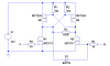
Here's an example:View attachment 39323
I found it at: **broken link removed**. They don't tell you how to get VGH, which should be 7-12 volts above your top power rail, or in your case it would be 19-24 volts. It needs to have a generous peak current capability (0.1uF or more) but only needs to provide a few mA continuous. If you change R7, R10, and R11 to be 33k, it should still be fast enough for your circuit since you aren't changing directions frequently or rapidly.

[edit]The gate voltage should be independently, you can't hook two gates together.[/]

I wish I could offer a simpler solution, but this is why for one-offs I use the slightly more expensive P-channel MOSFETs instead.

In your application, I would seriously consider small relays.


Yeah this seems to be becoming more and more complicated using the FETs to switch the polarity for the motor the more I learn what's needed to make this particular circuit work.

I'm a bit new to relays in general, as I've never worked with them, but how much simpler would that make my circuit compared to the one I have now? Reason I ask is, I'm still in the prime state of my project, so this is the time to make major changes if needed, so if I need to simply ditch my current circuit and go with a easier more simplified version, then that's what I'll do :)
 
It does get much simpler if you consider P-channel MOSFETs for Q1, Q2. I don't remember how much current the motor needs, nor do I remember if P-channel devices were offered earlier.
 
It does get much simpler if you consider P-channel MOSFETs for Q1, Q2. I don't remember how much current the motor needs, nor do I remember if P-channel devices were offered earlier.

Yeah I remember reading that in another forum, but the only problem I have with the P-channel is, I'm not sure which ones to get, and which N-channel to get. Like, do both the P/N channel FETs need to have the same volts/amps ratings or is there another special rule for this?

I haven't gotten my linear actuator in the mail yet so I can see how much current it uses, but all I do know is that it is a 12volt linear actuator from the website description.
 
If you put your location (in your UserCP) we might be able to help you find reasonable devices.

For example, If your motor is less than 2A this is a nice P-channel device: IRF9Z24 11A 60 Volt 0.28 Ohm HEXFET Power MOSFET (IR)-The Electronic Goldmine and this is a nice cheap N-channel: IRFZ10 60V N-Channel MOSFET (IR)-The Electronic Goldmine

Nothing special about these except they are less than $1 and Goldmine is in my bookmarks.

Okay, so it seems you picked two FETs with close/similar ratings(regarding volts/amps) for the P/N-channel, and yeah I'll add my location (Tennessee) soon too.

I usually order my components from Jameco.com but I hate they are located in California, and of course RadioShack have sucky parts or just overpriced.

My linear actuator is able to lift 1,000+ pounds so I'm thinking it can use quite a bit of amps :), but I wont be lifting anything that heavy. So yeah, I'll try to find out that info as I understand until that's found out I can't really proceed, but it's good to know using P/N Fets will simplify this A LOT!

Thanks again, and I'll be posting back here once I find that info out...
 
Okay, so I called and found out the Amps for my linear actuator and they are as follows:

No Load: 1.8A (nothing on it)
Full Load: 12A (full weight on it)

So now I need to find a P/N-Channel FET that can handle I'd say 20A maybe to be on the safe side and 20v or more?

If so shouldn't the following two FETs work for my system:

P-Channel: Transistor MOSFET P Channel 55V 31A 3-Pin (3+Tab) TO-220AB

N-Channel: 55V 98A SINGLE N-CHANNEL HEXFET POWER MOSFET IN A TO (Same ones in my circuit above)

Now my N-Fet can handle way more current/voltage than the P-Channel, but that shouldn't be a problem right? Just as long as each one is above the required Amps/Volts my Actuator needs?

Here is my updated schematic:
screenshot.6..jpg
 
Last edited:
Mosfets need about 10-12V to be fully on/open, it seems your only feeding them 7, which might be a reason as to why they are getting hot :)

ahhhh... you can't make a blanket statement like that. I used one today that has a gate threshold voltage of 2.4V!!!!


check the part's spec sheet!
 
ahhhh... you can't make a blanket statement like that. I used one today that has a gate threshold voltage of 2.4V!!!!


check the part's spec sheet!

So should I be fine not having two power sources to get this circuit to work, and check out my updated circuit above as unlike the orginal circuit where I'm using only N-Channel FETs I'm not using P/N-Channel FETs. I haven't fully learned why using P/N-Channel FETs are ideal for changing polarity for a motor but have seen a lot of people recommend it.

At this point I'm just wondering if my circuit current is hooked up right and do I need to do anything else for my solar tracker to work properply. At the moment I just care for it to rotate left to right, and later on I'll add-on to the circuit to make the solar tracker a bit smarter :)
 
p channel FETs are used to SOURCE current (top side) and n channel FETs are used to SINK current (bottom side). Unfortunately, they are backwards in the way you turn them on, so your new circuit won't work either.
 
You should look at the circuit given in post #13 of this thread.

Okay, so basically I just need to flip my P-FETs around so that the source end is going to Vcc, at least I think that's what it looked like in that schematic.

Attached is my updated schematic. I'm not sure what all the resistor and diodes on that schematic do yet, but just trying to take this one step at a time hehe :) My goal is just to at least get it functioning even though it'll be a rough version, and then clean it up and make it better.

But yeah that's what I had wrong in my previous circuit right mneary, the P-Fets flipped around wrong?
screenshot.1..jpg
 
hi , just wanted to update you .
i am changing my ckt to one that would drive stepper motor .
To drive stepper motor i gonna use ULN2808.
 
The P-FETs need to be driven with the opposite polarity than the N-FETs. The circuit that I copied does all of that for you.
 
The P-FETs need to be driven with the opposite polarity than the N-FETs. The circuit that I copied does all of that for you.

Alright, but just so I'm sure I'm on the same page here, are my FETs at least turned the right way, as that's one of the prime issues I seem to always have when creating these H-Bridges? I've looked at the schematic you provided and they appear to be, but just need that info confirmed :) then I'll move on to trying to figure out how exactly to add in those resistors/doide into my own circuit correctly.

From your statement, I'm guessing you are saying that all the resistors, and the diode in that circuit is what helps drive the P-FETs in an opposite polarity?
 
Last edited:
I went ahead and updated my schematic to match the one you gave me, but considering I know only about 70% of what's going on with that H-Bridge I'm not 100% sure I implemented in my design correctly lol :)

screenshot.2..jpg

I was a bit in a hurry and wanted to update it before I head to bed, but for the most part I think it's setup right.
 
Okay so after testing the circuit, the diode seem to be preventing one polarity from working, so I ended just simply taking that diode out of the circuit and leaving the rest of the components. Refer to the schematic below:

screenshot.3..jpg

Now the only issue I see now is, when both switches are open, you see both LEDs are "ON" so that means the motor will be turning against itself, which I'm sure isn't good lol. So my next question is, what can I do to prevent that?
 
Now the only issue I see now is, when both switches are open, you see both LEDs are "ON" so that means the motor will be turning against itself, which I'm sure isn't good lol. So my next question is, what can I do to prevent that?
The diode that you removed is intended to prevent this.
 
will somebody tell me how you keep from blowing up your LEDs... if you connect them that way, the first time you put 12V to an anode it'll be very very bright, for about 1msec, then it'll smoke...
 
will somebody tell me how you keep from blowing up your LEDs... if you connect them that way, the first time you put 12V to an anode it'll be very very bright, for about 1msec, then it'll smoke...


lol yeah I know, but you really don't have to worry about that when you are just simulating it on multisim, but yeah in the real word, I would never just throw a LED in the circuit like that unprotected it :)

I'm going to try the two diodes idea first to see how that goes.
 
Status
Not open for further replies.

Latest threads

New Articles From Microcontroller Tips

Back
Top