Their solar tracking rate might not be that accurate, but mine is.
Even driven from a xtal you can tune it to one PPM accuracy, which is about "X" / 1000000 per adjustment step. Alternatively running from a GPS lock it gets about a hundred times more accurate than that!
Anyway if you prefer a closed loop system to really accurate clockwork tracking that's up to you. In that case I think sensor design, reliability and cleaning will be critical.")
Hi Roman,
Well their Solar tracking is quite accurate but the most problems with amateur solar imagers is the perfect alignment of the mounts. Do not think it is that easy. Also a lot more para meters do play a role here., especially refraction. The closer the object ois to the horizon its speed decreases. See here for example the Special King Rate which adjust the speed continously from Zenith to horizon, etc, etc, etc.
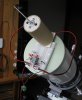
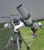
What I intend to do is to just add a guider to an already existing tracking device of the Sun. I have read your page. Very interesting. Will keep getting ideas from your Website too.
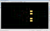
I made some tests this weekend and the idea I am develipong seems to go in the right way. As you said precisión here is the Key word.
The interesting thing of this project is what I have learned in the last weeks and days.
Last edited: